NWA-6500 Series - User Guide, Rev. 1.4
// 25
4.4.
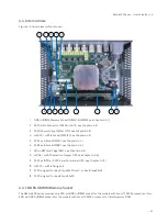
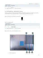
Internal View
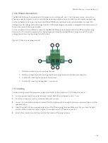
Figure 4: Internal view (without cover)
1
DDR4 UDIMM Memory Socket (DIMM1 & DIMM2, see Chapter 4.4.1)
2
SATA Data Connector (SATA1 or SATA, see Chapter 4.4.2)
3
SATA Power Output Wafer (CN1, see Chapter 4.4.2)
4 mSATA / mPCIe Socket (MPCIE1, see Chapter 4.4.3)
5
M.2 Key A Socket (M2A1, see Chapter 4.4.4)
6
M.2 Key B Socket (M2B1, see Chapter 4.4.4)
7
Micro SIM Card Cage (SIM1, see Chapter 4.4.5)
8 mPCIe / mSATA Selection Jumper (JP5, see Chapter 4.4.6)
9
M.2 Key B PCIe / SATA Selection Jumper (JP4, see Chapter 4.4.7)
10 mSATA / mPCIe fixing bolt
11 M.2 fixing bolt for Key A type22x30 and / or Key B type22x42
12 M.2 fixing bolt for Key B type 22x80
4.4.1.
DDR4 UDIMM Memory Socket
The NWA-6500 Series provides one 288-pin DDR4 UDIMM socket for the models with Atom® C3338 processor or two
288-pin DDR4 UDIMM sockets for the models with Atom® C3538 processor to install memory RAM.
1
1
2
2
3
4
5
6
8
9
10
12
7
11

