NWA-6500 Series - User Guide, Rev. 1.4
// 27
Jumper 1 Position
Description
Pin 1-2
Pin 2-3
-
X
mSATA
“X” = Jumper set (short) and “-” = jumper not set (open)
4.4.7.
M.2 Key B PCIe / SATA Selection Jumper
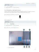
The Jumper JP4 can switch the M.2 Key B socket (M2B1) to PCIe & USB 3.0 mode for 3G / 4G modem card installation
or SATA & USB 3.0 mode for M.2 SSD installation. The default setting is in "PCIe & USB 3.0" mode.
Figure 6: M.2 Key B PCIe / SATA Selection Jumper (JP4)
Table 4: Pin Assignment JP4
Jumper 1 Position
Description
Pin 1-2
Pin 2-3
X
-
PCIe & USB 3.0
-
X
SATA & USB 3.0
“X” = Jumper set (short) and “-” = jumper not set (open)
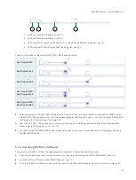
Figure 7: Internal view - Inner side of the access cover
1
2.5" HDD / SSD Bracket
2
3
1
1
2
2
3
3

