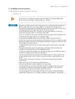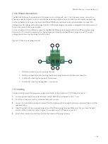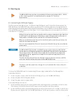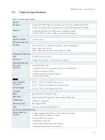
NWA-6500 Series - User Guide, Rev. 1.4
// 26
4.4.2.
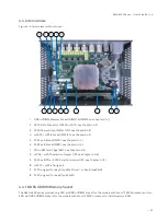
SATA Data Connector & SATA Power Output Wafer
The NWA-6500 Series provided one SATA data connector for models with DC jack or two SATA data connectors for
models with Phoenix connector to install a 2.5" SATA HDD / SSD. A SATA power output wafer is provided to power the
hard disk and a bracket is attached on the inner side of the access cover for holding and fixing the hard disk.
4.4.3.
mSATA / mPCIe Socket
The NWA-6500 Series reserves one mPCIe / mSATA combo socket for expansion with a full-sized mPCIe 3G / 4G or
WLAN card by default. To switch to mSATA for SSD installation, see jumper setting at JP5 in Chapter 4.4.6.
4.4.4.
M.2 Socket
The NWA-6500 Series reserves two M.2 sockets. One is Key A allowing the expansion with a Type 22x30 Wi-Fi,
Bluetooth, NFC and / or WiGig card. The other is Key B allowing the expansion with a Type 22x42 / Type 22x80 SSD
card or 3G / 4G card which can be switched via the Jumper JP4 (see Chapter 4.4.7).
The fixing bolt marked in Figure 4, pos. 11 can be used to fix either a Type 22x30 card
installed in M.2 Key A socket and / or a Type 22x42 card installed in M.2 Key B socket with an
additional fixing bolt extension.
4.4.5.
Micro SIM Card Cage
The baseboard of the NWA-6500 Series is equipped with a Micro SIM card cage, which can be switched to connect to
either the mPCIe socket or M.2 Key B socket via the BIOS setting (see Chapter 12.2.2).
To avoid damage to the Micro SIM card, insert the Micro SIM card before you turn the
power on and remove the Micro SIM card after you turn the power off.
4.4.6.
mPCIe / mSATA Selection Jumper
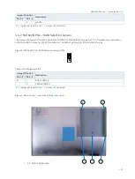
The Jumper JP5 can switch the mPCIe / mSATA combo socket (MPCIE1) to mPCIe mode for 3G / 4G / Wi-Fi card
installation or mSATA mode for mSATA SSD installation. The default setting is in "mPCIe" mode.
Figure 5: mPCIe / mSATA Selection Jumper (JP5)
Table 3: Pin Assignment JP5
Jumper 1 Position
Description
Pin 1-2
Pin 2-3
X
-
mPCIe
2
3
1


