6
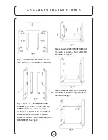
Fig. A
Step 2: Attach PANEL E to PANEL G and J
with 1 KD screw. Attach PANEL F to PANEL
H and K with 1 KD screw. See Fig. B.
Fig. B
Step 3: Attach 2 x 4-HOLES WOOD CON-
NECTORS [S] to PANEL E and F with 4 KD
SCREWS (2 screws for each wood con-
nector). Attach Panels E, G and J to BASE
PANEL [B] with 2 KD SCREWS. Attach
PANELS F, H and K to BASE PANEL [B] with
2 KD SCREWS. See Fig. C.
Fig. C
Step 4: Attach LOWER FRONT PANEL [D]
to the unit as shown in Fig. D with 2 KD
SCREWS. See fig. D.
Fig. D
Step 5: Attach UPPER FRONT PANEL [C]
to the unit as shown in Fig. E with 6 KD
SCREWS. See fig. E.
Fig. E
A S S E M B LY I N S T R U C T I O N S
Summary of Contents for M850P-26FDC
Page 13: ...13...


