


April 29, 2013
7075-205
Page 7
R
Voyageur Grand
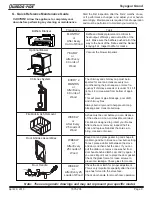
• Frequency:
When ash reaches the top of the brick
covers (should not spill over covers). Leave 1/4 inch
(6mm) of ash in the bottom of the firebox.
• By:
Homeowner
A. Disposal of Ashes
• Place ashes in a metal container with a tight-fitting lid.
• The closed container should be placed on a noncombustible
floor or on the ground, well away from all combustible
materials, pending final disposal.
• If the ashes are disposed of by burial in soil or otherwise
locally dispersed, they should be retained in the closed
container until all cinders have thoroughly cooled
WARNING! Risk of Fire! Ashes could contain hot embers.
B. Chimney and Chimney Connector
Inspection/Cleaning
• Frequency:
Every 2 months during heating season or
as recommended by a certified chimney sweep; more
frequently if chimney exceeds or is under 14-16 feet (4.3
to 4.8m) measured from bottom of appliance.
• By:
Certified chimney sweep
• Remove all ash from the firebox and extinguish all hot
embers before disposal.
• Allow the appliance to cool completely.
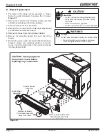
•
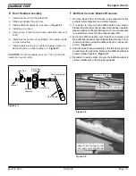
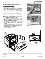
If your type of installation involves a full reline of the
chimney, it will be necessary to either remove the baffle
from the insert, or remove the insert from the fireplace
and disconnect the vent prior to cleaning the chimney.
Refer to
page 23
in this manual for instructions on Baffle
Removal.
•
If your type of installation is direct connect within a masonry
chimney, the insert will need to be pulled out from the
fireplace and disconnected from the flue prior to cleaning
the chimney.
• The creosote or soot should be removed with a brush
specifically designed for the type of chimney in use.
• Clean out fallen ashes from the firebox.
• It is also recommended that before each heating season
the entire system be professionally inspected, cleaned
and repaired if necessary.
WARNING! Risk of Fire!
Do not use chimney cleaners or flame colorants in your
appliance. It will corrode your pipe.
Creosote - Formation and Need for Removal
•
When wood is burned slowly, it produces tar and other
organic vapors, which combine with expelled moisture
to form creosote.
•
The creosote vapors condense in the relatively cool
chimney flue of a slow-burning fire.
•
As a result, creosote residue accumulates on the flue
lining. When ignited this creosote makes an extremely
hot fire.
•
The chimney and chimney connector shall be inspected
every two months during the heating season to
determine when a creosote buildup has occurred.
•
When creosote has accumulated it shall be removed to
reduce the risk of a chimney fire.
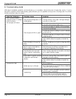
C. Appliance Inspection - Routine
•
Frequency:
Every 2 months at the same time the
chimney and chimney connector are inspected.
• By:
Homeowner
Check for:
• Cracks in glass
• Door handle - smooth cam operation
• Baffle and ceramic blanket correct placement
•
Baffle for warpage
• Firebrick for cracks, broken or crumbly
• Door gasket. (Dollar bill test). Place a dollar bill be
-
tween the stove and the door and then shut the door. If
you can pull the dollar bill out, replace the door gasket.
• Glass frame for loose screws
D. Cleaning Plated Surfaces
• Frequency:
As desired
• By:
Homeowner
• Clean all the fingerprints and oils from plated surfaces
BEFORE
firing the appliance for the first time.
• If not cleaned properly before lighting your first fire, the
oils can cause permanent markings on the plating.
• After the plating is cured, the oils will not affect the finish
and little maintenance is required.
•
Wipe clean as needed.
CAUTION! Do not use polishes with abrasives. It will
scratch plated surfaces.
2
Maitenance & Service