Quadra-Fire VOYAGEUR GRAND INSERT GRAND-MBK-AU Owner'S Manual Download Page 28

Page  28

7075-205

April 29, 2013

R

Voyageur Grand

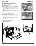
8.  The power cord is now disconnected from the blower 

control plate.  Pull the cord out through the right side 

of the appliance.

Route Cord Through 

Retainer Clip

Grommet

9.  Insert  the  power  cord  throught  the  left  side  of  the 

appliance in the hole contains the grommet.  Pull the 

connection ends to the right side.  Route the power 

cord through the retainer clip.

Strain Relief

10. Replace  the  strain  relief  on  the  power  cord  in  the 

same position as before.  Locate the indentation on 

the cord made by the strain relief.  Once replaced, 

push the strain relief back into the control plate.

White Wire

Black Wire

Fiber 

Wrapped 

Wire

Green 

Grounding 

Wire

11. Connect the white wire on the power cord into the 

fiber wrapped wire on the wire harness.  Connect the 

black wire on the power cord to the white wire on the 

rheostat.  Re-attach the green ground terminal to the 

control plate. 

12. Insert  the  control  plate  assembly  back  into  the 

appliance as shown.  Tilt the assembly forward and 

then lift up and rotate the bottom towards the front 

of the appliance at the same time ensure that the 

snap disc holder is properly seated.  Secure plate 

to the appliance.

Figure 25.1

Figure 25.2

Figure 25.3

Figure 25.4

Figure 25.5

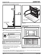
Route Wires through Retainer Clip

Replace Screws in Hold Down Bracket

13. Push  in  the  blower  and  hold  down  bracket  into 

appliance matching up the tab on the bracket and 

placement  slot  on  the  appliance.  Secure  bracket 

and  reconnect  blower  wires  (no  polarity  to  worry 

about) routing wires through the retainer clip.

Figure 25.6

Summary of Contents for VOYAGEUR GRAND INSERT GRAND-MBK-AU

Page 1: ...ngle between 0 30 inclusive For installations with a ceiling angle greater than 30 refer to Fig 18 1 21 1 21 2 and AS NZS 2918 2001 4 6 3 b Ceiling Plate may vary in size depending on ceiling angle Pl...

Page 2: ...joyment in the warmth and comfort of your hearth appliance Thank you for choosing Quadra Fire VOYAGEUR GRAND Serial No 007057 U S ENVIRONMENTAL PROTECTION AGENCY Export stove May not be operated withi...

Page 3: ...nces A Appliance Dimensions 16 B Clearances to Combustibles UL and ULC and Hearth Protection Requirements 17 C Alternate Floor Protection Calculation 18 Section 6 Chimney Systems A Venting Systems 19...

Page 4: ...OW HIGH BURN RATE CONTROL Upper Right Corner LOAD WOOD ADD NEWSPAPER ADD KINDLING ADD MORE WOOD SECURELY LATCH THE DOOR 4 LIGHT THE PAPER OPEN AIR CONTROLS REDUCE AIR CONTROL Set to desired heat outpu...

Page 5: ...burn rate instructions below and refer to Figure 5 1 NOTE These are guidelines Actual settings may vary with type of wood chimney draft altitude and other variables E Blower Control Box Snap Disc Oper...

Page 6: ...within close proxim ity approximately 4 ft 1 2m of appliance Can reverse air flow blowing hot air into appliance cavity Can damage appliance blower due to overheating 6 The blower is equipped with a...

Page 7: ...rom the firebox It is also recommended that before each heating season the entire system be professionally inspected cleaned and repaired if necessary WARNING Risk of Fire Do not use chimney cleaners...

Page 8: ...way open for 15 20 min utes should remove the built up coating E Glass Cleaning CAUTION Handle glass assembly with care Glass is breakable Avoid striking scratching or slamming glass Avoid abrasive c...

Page 9: ...he ashes in a non combustible container Firebrick is designed to protect your firebox After ashes are removed inspect the fire brick and replace firebricks that are crum bling cracked or broken WEEKLY...

Page 10: ...ding a Fire Section Check for adequate vent height refer to Chimney Height Section Open window below the appliance towards the wind Wood condition is too wet too large Use dry seasoned wood refer to S...

Page 11: ...by impact or misuse WARNING Risk of Fire or Injury Use only glass that is specified in the manual DO NOT replace with any other material Glass breakage will occur CAUTION Handle glass with care Inspec...

Page 12: ...ld down bracket s screws are completely seated in the grom ments Insert the locating tab in the hold down bracket into the placement slot Shock Risk Do NOT remove grounding prong from plug Plug direct...

Page 13: ...right side Remove the baffle boards and ceramic blanket together Figure 9 3 4 Re install in reverse order Be sure the baffle boards and ceramic blanket are in their proper positions E Door Handle Ass...

Page 14: ...oil for at least 15 minutes before trying to remove them 4 Slide the tube channel assembly all the way to left until it is off the threads Drop the right side down then slide the assembly back to righ...

Page 15: ...act your dealer if any irregularities are noticed 3 All safety warnings have been read and followed 4 This Owner s Manual has been read 5 Floor protection requirements have been met 6 Venting is prope...

Page 16: ...l Sizes A B Metal Surround w Cast Trim STD 1080 mm 762 mm Metal Surround w Cast Trim LRG 1219 mm 864 mm All Cast Surround 1016 mm 762 mm Metal Surround w Standard Trim STD 1092 mm 787 mm Metal Surroun...

Page 17: ...QUIREMENT FIREPLACE FRONT SURFACE SIDE TRIM 3 max depth SIDE WALL MANTEL 12 max depth TOP TRIM 3 4 max depth MANTEL DEFLECTOR REQUIRED MINIMAL REQUIREMENT FOR EXTENSION PROTECTION THE HEARTH THERMAL P...

Page 18: ...AS NZS 2198 2001 3 2 3 B Clearances to Combustibles Cont d Required Protection Suggested Protection NOTE Keep Ashlip Clear of Ashes NOTE Clearances may only be reduced by means approved by the regula...

Page 19: ...eable for cleaning and re installation NOTE Refer to chimney liner manufacturer for recom mendations on supporting the liner Installation into fireplaces without a permit will void the listing A Venti...

Page 20: ...he safety of your insert by directing the hot gases up the flue but will also help increase the unit s efficiency and decrease creosote deposits in the chimney When a connected flue or liner is in use...

Page 21: ...ont of Smoke Chamber Damper Plate Removed or Fastened in Open Position Seal with Non Combustible Material Minimum Clearance in Accordance with Insert Listing Floor Protection in Accordance with Insert...

Page 22: ...ssembly 5 Remove the outside air cover plate B on outer can and dis card Figure 19 2 6 Install optional flex adapter to outer can with the same screws Do not use plastic wire ties that come with the k...

Page 23: ...install the screws to secure in place D Leveling Legs B Optional Elbow Flue Adapter Installation Optional use of a Simpson Duravent 15 Universal Elbow Part Number 4615 may be purchased directly throu...

Page 24: ...ance top Secure in place Figure 21 2 7 Use the strain relief in the surround side for blower cord installation and use the cover plug to insert into the hole where the blower cord is not installed Fig...

Page 25: ...wered 102 to 152 millimeters long Phillips head screw driver pliers G Standard Surround Cast Trim Kit 4 Felt Vibration Insulation Pads Secure Surrounds to Cast Trim Kit Attach Magnet before installing...

Page 26: ...le Remove the shield and re install using the second right hole Figure 43 2 5 Position the trim on the appliance matching up the mounting brackets with the slots on the appliance 6 Attach the surround...

Page 27: ...the 2 screws at the top of the control plate Push the bottom of the control plate to the inside of the appliance and partially remove the control plate assembly White Wire Black Wire Figure 24 2 5 Loc...

Page 28: ...ire 11 Connect the white wire on the power cord into the fiber wrapped wire on the wire harness Connect the black wire on the power cord to the white wire on the rheostat Re attach the green ground te...

Page 29: ...WHERE SUCH ACTION IS CONSIDERED THE MAN UFACTURER SHOULD BE CONSULTED IN THE FIRST INSTANCE CAUTIONS CRACKED AND BROKEN COMPONENTS e g GLASS PANELS OR CERAMIC TILES MAY RENDER THE INSTALLATION UNSAFE...

Page 30: ...rage under this manufacturer s warranty begins on the date of first occupancy of the dwelling or six months after the sale of the product by an independent authorized HHT dealer distributor whichever...

Page 31: ...plied with the appliance or any other components not expressly authorized and approved by HHT 8 modification of the appliance not expressly authorized and approved by HHT in writing and or 9 interrupt...

Page 32: ...CC DO NOT DISCARD THIS MANUAL CAUTION Important operating and maintenance instruc tions included Leave this manual with party responsible for use and operation Read understand and follow these instruc...

Reviews: