


April 29, 2013
7075-205
Page 19
R
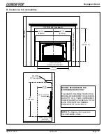
Voyageur Grand
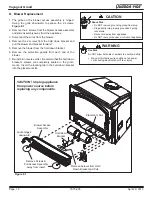
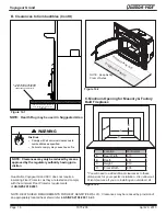
6
Chimney Systems
3. Both methods must be removable and replaceable
for cleaning and re-installation.
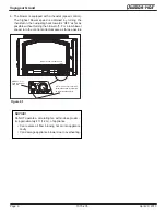
• When possible, install an airtight clean-out door to the
rear of the smoke shelf.
NOTE:
Masonry chimneys are significantly less than ideal
for venting solid fuel appliances. A masonry chimney is not
subject to any temperature limit test, therefore a full reline is
strongly recommended.
E. Prefabricated Metal Chimney
The chimney can be new or existing, masonry or prefabricated
and must meet the following minimum requirements:
• Must be minimum 152 mm inside diameter of high
temperature chimney.
• Must use components required by the manufacturer for
installation.
• Must maintain clearances required by the manufacturer
for installation.
• Refer to manufacturers instructions for installation
•This insert is listed to UL 1482 Standard and is approved
for installation into listed factory-built solid fuel fireplaces
listed to UL 127 conforming to the following specifications
and instructions:
•The original factory-built clearance fireplace chimney cap
must be re-installed after installing the approved chim
-
ney liner meeting type UL 103 HT requirements (2100°F)
per UL 1777.
•The liner must be securely attached to the insert flue collar
and the chimney top.
•The air flow of the factory-built solid fuel fireplace system
must not be altered. The flue liner top support attach
-
ment must not reduce the air flow for the existing air-
cooled chimney system.
•No dilution air is allowed to enter the chimney.
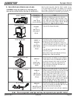
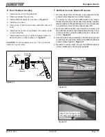
1.
Secure the fireplace damper in the open position. If
this cannot be accomplished, it will be necessary to
remove the damper.
2. Seal damper area of chimney around chimney
connector with a high temperature sealant or seal
insert against the face of the fireplace.
3. Both methods must be removable and replaceable
for cleaning and re-installation.
NOTE: Refer to chimney liner manufacturer for recom-
mendations on supporting the liner. Installation into
fireplaces without a permit will void the listing.
A. Venting Systems
Chimney Connector:
It is also known as flue pipe or stove
pipe. It must be 152 mm minimum diameter stainless steel
connector pipe.
Chimney
: The chimney can be new or existing, masonry
or prefabricated and must meet the following minimum
requirements as specified below.
WARNING! Risk of Fire!
Follow venting manufacturer’s clearances and instructions
when installing venting system.
B. Inspections
Existing chimneys should be inspected and cleaned by a
qualified professional prior to installation. The chimney must
not have cracks, loose mortar or other signs of deterioration
and blockage.
C. Larger Chimneys
Hearth & Home recommends that chimneys with larger
diameters than 152 mm be fully relined. An oversized
flue can affect draft and impair performance and will allow
increased build-up of creosote which is why a full reline is
stongly recommended.
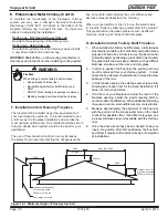
D. Masonry Chimney
• Must have at least 16 mm fireclay lining joined with
refractory cement.
NOTE: Installations into a clay flue without a
stainless steel liner may reduce draw which affects
performance, will cause the glass to darken and
produce excessive creosote and create start-up
issues.
•
The masonry wall of the chimney, if brick or modular block,
must be a minimum of 102 mm nominal thickness.
•
A chimney of rubble stone must be at least 305 mm thick.
• Should be lined with a 152 mm stainless steel flue liner
to improve performance and reduce creosote build-up
and difficulty starting a fire.
•
An equivalent liner must be a listed chimney liner system
or other approved material.
• No dilution air is allowed to enter the chimney.
1.
Secure the fireplace damper in the open position. If
this cannot be accomplished, it will be necessary to
remove the damper
2. Seal damper area of chimney around chimney
connector with a high temperature sealant or seal
insert against the face of the fireplace.