background image

 26 


                       7080-166B 


   April 18, 2018

TREKKER

EXHAUST

TEMPERATURE

SERIAL PORT

(SERVICE & 

BLUETOOTH CABLE)

FUSE

M

M

M

110 V

LINE

NEUTRAL

IGNITER

FEED MOTOR

EXHAUST 

BLOWER

CONVECTION 

BLOWER

VACUUM

SWITCH

SNAP

DISC

BLACK

WHITE

PURPLE

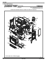
PURPLE

BLUE

BLUE

ORANGE

WHITE

BLACK

BLACK

SNAP

DISC

HOPPER

SWITCH

ENCODER (SPEED SENSOR)

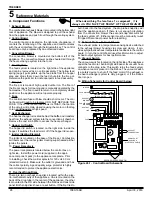
Figure 26.1 - Control Board Schematic

burn back into the feed system, the drop tube snap disc will 

shut the appliance down. If there is not enough circulation 

from the convection blower the second snap disc will shut 

the feed system off.  Either sensor must be manually re-set 

if tripped. Disconnect power before resetting. 

12. Exhaust Probe - Exhaust Blower 

The exhaust probe is a temperature-sensing device attached 

to the exhaust blower housing via screw and clamp.  It pro

-

vides sympathetic exhaust temperature feedback to the control 

board.  In turn, the control board uses this information to adjust 

its heat-output systems for best performance. 

13. Vacuum Switch 

The vacuum switch is located on the right side of the appliance 

under the feed motor, behind right side panel. Its vacuum hose 

connects to the drop tube. This switch turns the feed system 

on when vacuum is present in the firebox. The vacuum switch 

is a safety device to shut off the feed motor if the exhaust or 

the heat exchanger system is dirty, plugged, or if the firebox 

door is open. 

14. Wiring Schematic for Control Board (below)

When describing the location of a component, it is 

always AS YOU FACE THE FRONT OF THE APPLIANCE.

A. Component Functions 

1. 

Exhaust Blower 

The combustion (exhaust) blower is mounted in the bottom right 

rear of appliance. The blower is designed to pull the exhaust 

from the appliance and push it out through the venting system. 
2. 

Control Board 

The control board is located on the right side of appliance. It 

controls the functioning of the appliance and communicates 

with the user interface through the Bluetooth key. The control 

board can only be replaced by an authorized dealer. 

3. 

Convection Blower 

The  convection  blower  is  mounted  at  the  bottom  left  of  the 

appliance. The convection blower pushes heated air through 

the heat exchange system into the room. 

4. 

Feed System 

The feed system is located on the right side of the appliance 

and can be removed as an entire assembly. The hollow feed 

spring (auger) pulls pellets up the feed tube from the hopper 

area and drops them down the feed chute into the fire pot. 

Reference the parts list for individual parts in feed assembly . 

5. 

Fire pot 

The fire pot is made of high quality ductile iron. The floor of 

the fire pot opens for cleaning and is manually operated by the 

homeowner. The floor needs to return to a completely closed 

position or the appliance will not operate properly. 
6. 

Fuse 

The control board fuse will blow should a short occur. The con

-

trol board will need to be replaced. DO NOT REPLACE THE 

FUSE. If the control board fuse blows its TRIAC, that portion 

of the circuit, will remain closed causing the motor on that leg 

to run 

continuously 

at high speed. 

7. 

Heat Exchanger 

The heat exchanger is located behind the baffle and transfers 

heat from the exhaust system into the convection air chamber. 

Remove the cast iron baffle to access the heat exchanger. 

8. 

Hopper Lid Switch 

The hopper lid switch is located on the right side, inside the 

hopper. It switches the feed motor off if the hopper lid is open. 
9. 

Igniter (Heating Element) 

The igniter is mounted on the base of the fire pot. Combustion 

air travels over the red hot igniter creating super heated air that 

ignites the pellets. 
10. 

Power Receptacle 

The power receptacle is located below the control box on 

right side.  Install the power cord (supplied in the appli-

ance component pack) to the appliance receptacle.  Prior 

to installing, check the wall receptacle for 120 volt, 60 Hz 

(standard current). Make sure the outlet is grounded and has 

the correct polarity. A good quality surge protector is highly 

recommended to protect the appliance electronics.

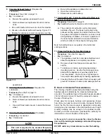
11. Overheat Snap Discs 

T

here are two overheat snap discs located within the elec-

tro-mechanical cavity of the appliance.  One is mounted on the 

back of the drop tube in the center of the appliance; the other 

is mounted in the RH side between the firebox and cast side 

panel. Both snap discs have a reset button. If the fire tries to 

E

Reference Materials
Summary of Contents for TREKKER-CSB

Page 1: ...not store or use gasoline or other flam mable vapors and liquids in the vicinity of this or any other appliance Do NOT burn garbage or flammable fluids such as gasoline naphtha or engine oil in room...

Page 2: ...doors tightly closed during operation Keep viewing and ash removal doors tightly closed during operation Conforme la norme ASTM E1509 12 Std Certifi la norme ULC S627 00 Room Heating Pellet Burning Ty...

Page 3: ...oved 7 2 Operating Instructions 8 A Fire Safety 8 B Non Combustible Materials 8 C Combustible Materials 8 D Fuel Material and Fuel Storage 8 E Before Your First Fire 9 F Filling the Hopper 9 G User In...

Page 4: ...struction warranty coverage begins on the date of first occupancy of the dwelling or six months after the sale of the product by an independent authorized HHT dealer distributor whichever occurs earli...

Page 5: ...t cover the following Changes in surface finishes as a result of normal use As a heating appliance some changes in color of interior and exterior surface finishes may occur This is not a flaw and is n...

Page 6: ...xhaust blower will run for about 45 seconds wait for it to stop before moving to manual feed 65 72 HEATING 5 From the OFF home screen press and hold the outer ring for 3 seconds to access the main men...

Page 7: ...liance Installation other than as instructed by Hearth Home Technologies Installation and or use of any component part not approved by Hearth Home Technologies Operating appliance without fully assemb...

Page 8: ...ate We recommend that you buy fuel in multi ton lots whenever possible However we do recommend trying various brands before purchasing multi ton lots to ensure your satisfaction Fuel Material Made fro...

Page 9: ...gin cycling on and off When the pellets are warming on the verge of igniting it is not uncommon for the firebox to fill with smoke Once ignition happens the smoke should quickly disap pear During this...

Page 10: ...eased during initial operation Curing of high temperature paint Open windows for air circulation Odors may be irritating to sensitive individuals CAUTION WARNING HOT SURFACES Glass and other surfaces...

Page 11: ...Space NOTICE Clearances may only be reduced by means ap proved by the regulatory authority having jurisdiction Mantel Avoid placing candles and other heat sensitive ob jects on mantel or hearth Heat m...

Page 12: ...blowers is from the impellers becoming dirty over time See maintenance and service section for maintaining and servicing What is the metal object with the bend in it that came inside the plastic bag I...

Page 13: ...maintained your appliance will give you many years of trouble free service Contact your dealer to answer questions regarding proper operation troubleshoot ing and service for your appliance Visit www...

Page 14: ...ainer with a tight fitting lid The container of ashes should be moved outdoors immediately and placed on a non combustible floor or on the ground well away from combustible materials pending final dis...

Page 15: ...t flat head screwdriver bottle brush ID hose 1 It is necessary to remove the baffle to gain access to the heat exchanger figure 15 2 Follow instruc tions for baffle removal on page 20 figure 20 2 2 Va...

Page 16: ...Frequency Monthly or after burning 50 bags By Homeowner a Be sure the appliance is allowed to cool b Open the front cast door and cycle the ash removal handle these should be inspected for functional...

Page 17: ...vacuum thor oughly c To minimize corrosion paint all exposed steel including cast iron Use the Touch Up paint sup plied with the appliance or purchase paint from your local dealer You must use a high...

Page 18: ...the top of the latch up to lock latch into place WARNING Cast iron is a very heavy material The baffle is made of cast iron and therefore is heavy and awkward at times to maneuver Clear and prepare y...

Page 19: ...blower slightly and lift up The blower will pass out the left side of the appliance Note You may need to loosen the surround to move it out of the way 7 Install replacement blower by placing the bott...

Page 20: ...stion blower You only need to remove the motor and impeller 4 Disconnect the wire from the control board connection and hall effect switch housing 5 Using an 7mm socket wrench or nut driver loosen the...

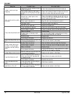
Page 21: ...itch operation Check hopper switch wires for integrity Check hopper lid on correctly Check hopper lid magnet is installed Safety snap disc is tripped not func tioning Check to make sure convection blo...

Page 22: ...re the exhaust probe to exhaust blower housing keeping its wire away from hot surfaces Defective probe Replace probe Control board is defective Replace control board Convection Blower fails to shut of...

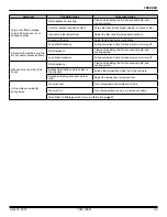
Page 23: ...Excessive fuel spilling over the fire pot and or excessive flame Dirty Appliance Clean unit including the fire pot exhaust path and venting system Feed Motor locked on Follow corrective action for fee...

Page 24: ...lid must be closed vacuum switch must be closed snap disc closed and feed motor must be plugged in Clear jam in feed tube Dirty appliance Clean unit including the fire pot exhaust path and venting sy...

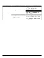
Page 25: ...USB extension cable not plugged in Bluetooth key not plugged in Replace Bluetooth Key Replace USB extension cable not plugged in Replace control board Bluetooth Key and user interface not paired Pair...

Page 26: ...appliance The convection blower pushes heated air through the heat exchange system into the room 4 Feed System The feed system is located on the right side of the appliance and can be removed as an e...

Page 27: ...April 18 2018 7080 166B 27 TREKKER B Maintenance Log Date of Service Performed By Description of Service...

Page 28: ...28 7080 166B April 18 2018 TREKKER Date of Service Performed By Description of Service...

Page 29: ...April 18 2018 7080 166B 29 TREKKER Date of Service Performed By Description of Service...

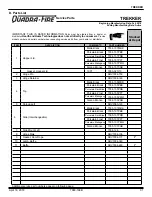
Page 30: ...e Feb 2018 Ending Manufacturing Date Active Pellet Stove TREKKER CSB TREKKER MBK TREKKER PBK TREKKER PDB TREKKER PFT TREKKER PMH Part number list on following page 1 18 2 1 3 4 5 6 7 8 9 10 11 12 13 1...

Page 31: ...34 157PFT Porcelain Mahogany 7034 157PMH Sienna Bronze 7034 157CSB Gasket Hopper Lid 10 FT 7000 320 10 2 Hinge Pin SRV7034 159 3 Hinge Retainer SRV7034 163 4 Top Matte Black 7034 155MBK Porcelain Blac...

Page 32: ...BER 12 Door Assembly SRV7080 022 12 1 Glass Retainer 7034 136 Y 12 2 Glass Assembly w Gasket 7034 007 Y Gasket Channel 1 8 x 1 1 4 x 10 7000 377 10 12 3 Hinge Female SRV450 2910 12 4 Door Latch Assemb...

Page 33: ...an Assembly SRV7034 069 Twin Ball Catch SRV7000 532 Y 17 Intake Shield 7034 224 Y 18 Firepot Riser Assembly SRV7080 082 18 1 Firepot Assembly SRV7080 083 Y 18 2 Gasket Firepot SRV7034 190 Y 18 3 Sprin...

Page 34: ...uum Switch SRV7000 531 Y Vacuum Hose 3 Ft cut to t SRV7000 373 Y 25 Control Board SRV7080 052 Y Wire Harness SRV7080 129 Y 26 Side Mount Right 7034 126 27 Shroud Right SRV7080 168 Y 28 Combustion Blow...

Page 35: ...0 071 Porcelain Mahogany SRV7080 068 Sienna Bronze SRV7080 067 Cleanout Tool 414 1140 Y Leveling Assembly 7000 000 Paint Touch Up Matte Black 812 0910 Porcelain Black 1 00 0022 Porcelain Dark Blue 1 0...

Page 36: ...purchased installed _________________________________________________________________________ Serial Number ____________________________________ Location on appliance ___________________________ Deal...

Reviews: