


16
7033-361B
November,
2021
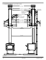
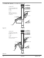
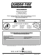
Flex Line
Wire Tie
Wire Tie
Flex Adapter
Termination
Cap
For Floor Installa-
tions Remove
Circular “Knock-Out”
in Base of Pedestal.
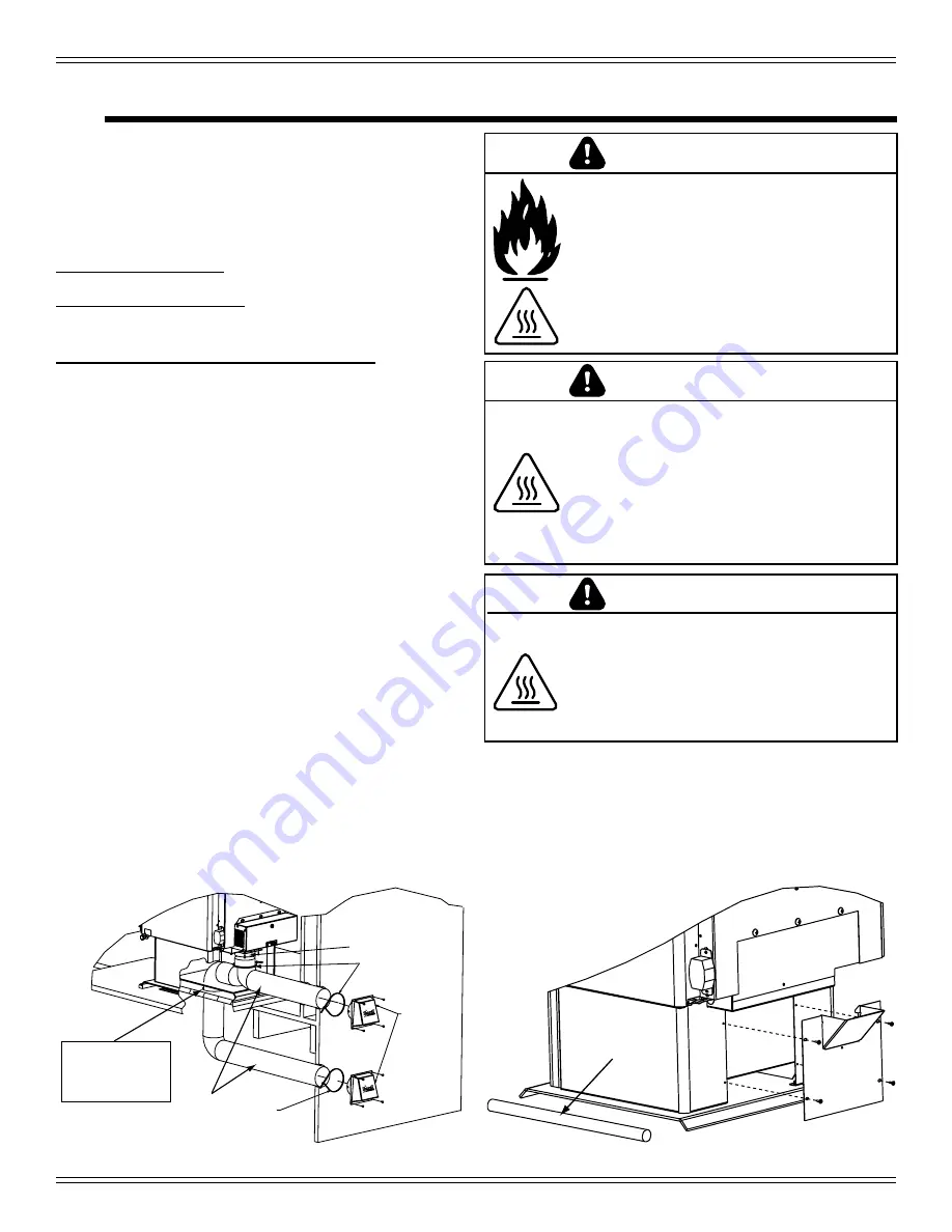
Figure 16.2
Cover
Plate
Rope to Seal
Pedestal
Items Needed for Installation (not supplied)
-
102mm flex aluminum pipe, or if using alternate
material, then it shall be made from durable,
non-combustible, heat resistant material up to
350oF. Cut the pipe to the required length for your
installation.
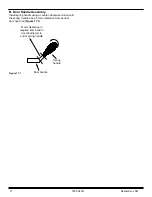
- Phillips head screw driver
- Silicone sealant
- Drills and saws necessary for cutting holes through
the wall or flooring in your home.
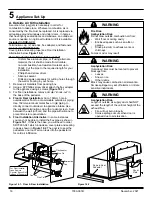
1. Remove all materials from packing box.
2.
Using a #2 Phillips screw driver attach the flex adapter
to the appliance using 4 screws
(Figure 16.1)
3.
For floor installations, remove circular” knock-out” in
the base of the pedestal.
4. Floor & Rear Installation:
Cut a 102mm hole in
outside wall or floor to accommodate outside air piping.
Use 102mm aluminum metal flex or rigid piping to
directly connect outside air to appliance intake. Use
the supplied termination cap with a rodent screen. Seal
between the wall (or floor) and the pipe with silicone to
prevent moisture penetration.
5. Floor Installation Alternative:
In some instances
you may not be able to install the flex pipe as show in
Figure 16.1
. If that is the case, you will need to order
SRV7033-041 which includes a cover plate and sealing
rope as shown in
Figure 16.2
. The goal is to seal the
pedestal so no room air can leak into the pedestal or
for cold air infiltration.
A. Outside Air Kit Installation
A source of air (oxygen) is necessary in order for
combustion to take place. Whatever combustion air is
consumed by the fire must be replaced. Air is replaced via
air leakage around windows and under doors. In homes
that have tightly sealed doors and windows, an outside air
source is needed. An optional Outside Air Kit is available.
Included in OAK-ACC:
Termination cap, (2) wire ties, flex adapter, and fasteners
Included in SRV7033-041:
Cover plate and sealing rope (see Floor Installation
Alternative below,
Figure 16.2
)
Figure 16.1 - Floor & Rear Installation
5
Appliance Set-Up
WARNING
Asphyxiation Risk.
Outside air inlet must be located to prevent
blockage from:
• Leaves
• Snow or ice
• Other debris
Block may cause combustion air starvation.
Smoke spillage may set off alarms or irritate
sensitive individuals.
WARNING
Fire Risk.
Asphyxiation Risk.
Do not draw outside combustion air from:
•
Wall, floor or ceiling cavity
• Enclosed space such as an attic or
garage
• Close proximity to exhaust vents or
chimneys
Fumes or odor may result
Asphyxiation Risk.
Length of outside air supply duct shall NOT
exceed the length of the vertical height of the
exhaust flue.
• Fire will not burn properly
• Smoke spillage occurs when door is
opened due to air starvation
WARNING
Summary of Contents for 31M-ACC-AU
Page 19: ...19 7033 361B November 2021...


