background image

 13 

      7033-361B 


November, 

2021

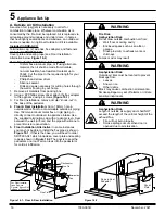
This product was designed for and tested on a 152mm 

chimney, 427-488cm high, (includes appliance height) 

measured from the base of the appliance. The further your 

stack height or diameter varies from this configuration, the 

greater the likelihood it may affect performance.

Chimney height may need to be increased by 2 - 3% per 

each 305 meters above sea level. It is not recommended 

to use offsets or elbows at altitudes above 1219 meters 

above sea level or when there are other factors that affect 

flue draft.

1.  Unpack the Flue Mounted Shield, detach the three 

brackets and familiarize yourself with the illustrations.

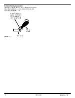
2.  Using a sharp knife or razor blade, carefully cut through 

the plastic film on the “inside face” where it meets the 

outer shield (refer sketch). Cut along the full length of 

the Flue Mounted Shield on both side, then peel off 

and fully remove the plastic film from the stainless steel 

inner shield.

3. 

Peel back and fully remove the plastic film from the 

outer shield.

4.  Fit the top bracket to the Flue Mounted Shield as 

illustrated ensuring the rear mid section of the bracket 

fits “outside” while the two outer sections of the bracket 

fit “inside”.

5. 

Fit the appropriate lower bracket to your wood fire.

Lower Bracket “5B suitable for all other wood fires 

without an inner rear heat shield. On certain model 

wood fires without a raised flue spigot it will be 

necessary to cut off both the lower outer legs from the 

bracket “5B” leaving the central tongue to locate inside 

the flue outlet only.

Two tabs are provided and if folded back at 90 degrees 

the bracket and Flue Mounted Shield will mount lower 

onto the appliance.

The Flue Mounted Shield then locates into the two 

notches provided n bracket “5B” as illustrated.

6. 

Once the Flue Mounted Shield is fitted in position onto 

either of the two lower mounting brackets, check to 

ensure a large gap is not present between the top of 

the wood fire and the base of the Flue Mounted Shield, 

as this may result in a hot spot on the rear wall directly 

behind the flue outlet. If your wood fire has a lift off 

top grill the Flue Mounted Shield should be raised 

sufficiently to enable the top grill to be removed.

7.  Using the pre-punched holes in the two tabs provided 

on the top bracket as guides, drill into the flue pipe 

and secure the top bracket to the flue pipe with two 

stainless steel rivets (not supplied).

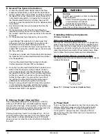
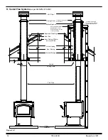
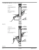
E. Chimney Height / Rise and Run

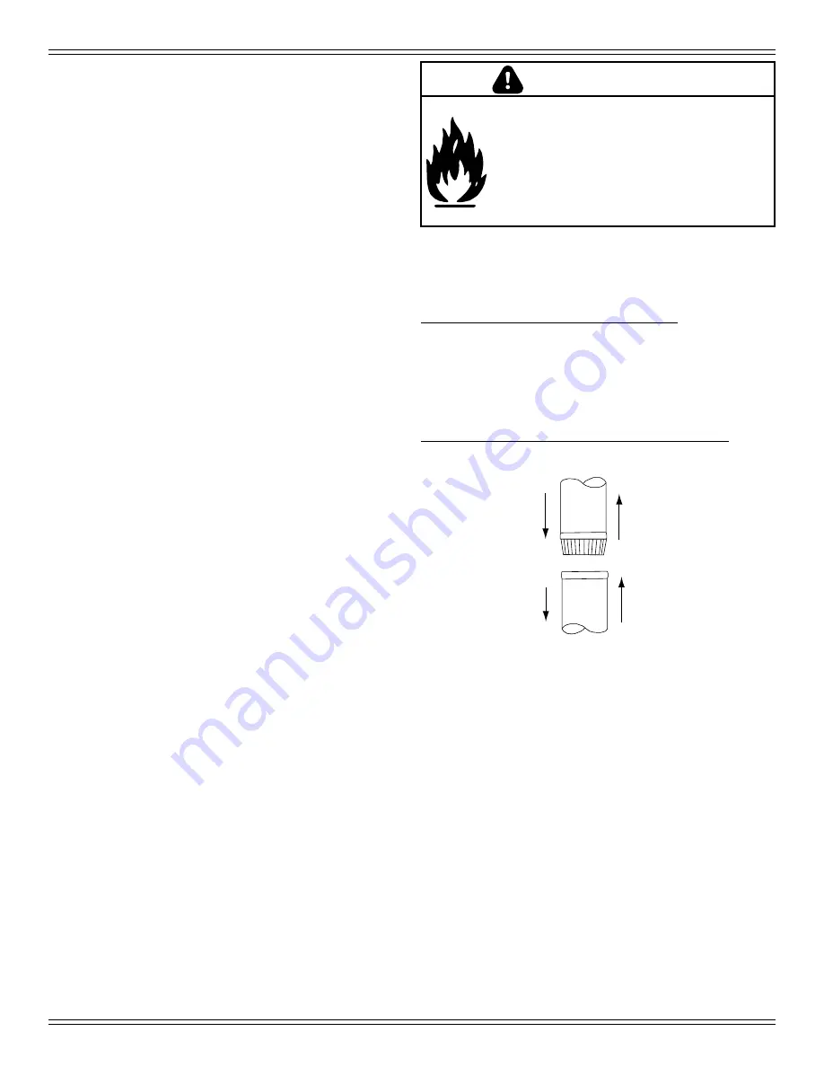
D. General Flue System Instructions

Flue Gas

Direction

Crimped

End

Toward

Appliance

Secure pipe sections with a

minimum of 3 screws

Figure 13.1 - Chimney Connector (Appliance Pipe)

F. Installing Chimney Components

Chimney Connector

Single wall connector or appliance pipe:

This must be at least 24 gauge mild steel or 26 gauge blue 

steel. The sections must be attached to the appliance and 

to each other with the crimped (male) end pointing toward 

the appliance. All joints, including the connection at the flue 

collar, should be secured with 3 sheet metal screws. Make 

sure to follow the minimum clearances to combustibles.

Factory-built listed chimney connector (vented):

The listed connectors must conform to each other to ensure 

a proper fit and seal.

G. Proper Draft

To be sure that your Quadra-Fire insert burns properly, the 

chimney draft (static pressure) should be approximately 

-2.54mm water column (W.C.) during a high burn and 

-1.016mm W.C. during a low burn, measured 152mm 

above the top of the insert after one hour of operation at 

each burn setting.

Fire Risk.

Do NOT pack insulation or other combustibles 

between spacers.

• 

ALWAYS maintain specified clearances 

around venting and spacers.

• 

install spacers as specified.

Failure to keep insulation or other material 

away from vent pipe may cause fire.

WARNING

Summary of Contents for 31M-ACC-AU

Page 1: ...h temperatures may ignite clothing or other flammable materials Keep clothing furniture draperies and other flammable materials away WARNING Fire Risk For use with solid wood fuel only Other fuels may...

Page 2: ...nimum Height of Flue System Exit 11 C Chimney Termination Requirements 12 D General Flue System Instructions 13 E Chimney Height Rise and Run 13 F Installing Chimney Components 13 G Proper Draft 13 H...

Page 3: ...th operating instructions in this manual NOTE Hearth Home Technologies manufacturer of this appliance reserves the right to alter its products their specifications and or price without notice Improper...

Page 4: ...consisting of at least two escape routes 5 A plan to deal with a chimney fire as follows 6 In the event of a chimney fire a Evacuate the house immediately b Notify fire department C Negative Pressure...

Page 5: ...ppliance Avoid installing the appliance near doors walkways or small isolated spaces Recessed lighting should be a sealed can design Attic hatches weather stripped or sealed Attic mounted duct work an...

Page 6: ...and given to the party responsible for use and operation Hearth Home Technologies recommends the following Photographing the installation and copying this checklist for your file That this checklist...

Page 7: ...m 676mm 796mm 501mm Figure 7 1 Front View Figure 7 3 Side View 648mm 749mm 383mm 533mm 278mm Figure 7 2 Top View 89mm 171mm 323mm A Appliance Dimensions NOTE Flue Collar size is 152mm inside diameter...

Page 8: ...e minimum Floor Protector requirements of AS NZS 2918 2001 WARNING Fire Risk Hearth pads must be installed exactly as specified High temperatures or hot embers may ignite concealed combustibles Fire R...

Page 9: ...3100 Millennium AU Wood Appliance INSTALLATION 345 175 668 360 76 225 800 1062 300 DOUBLE WALL PIPE A B C D E F G H 756 1197 I J 1469 K L NOTE Service Space In order to replace the tube channel assemb...

Page 10: ...ugh the warm space enclosed by the building envelope This helps to produce more draft especially during lighting and die down of the fire Penetrate the highest part of the roof This minimizes the affe...

Page 11: ...3000mm or less more than 3000mm 600mm minimum NOTICE Chimney performance may vary Trees buildings roof lines and wind conditions affect performance Chimney height may need adjustment if smoking or ove...

Page 12: ...ermination height The option of outer casing slips to be taken into account 6 Flash the outer casing to the roof material with the appropriate approved flashing 7 If using an outer inner casing combin...

Page 13: ...he Flue Mounted Shield is fitted in position onto either of the two lower mounting brackets check to ensure a large gap is not present between the top of the wood fire and the base of the Flue Mounted...

Page 14: ...een flue pipe casing combustible material Non combustible material Hebel block or 12mm Promina board or similar under the flashing 25 25 Approved Flashing Roof Line Inner Casing 200mm above roof line...

Page 15: ...x flue distance of the ceiling plate ADD Cowl Casing Cover Spider Bracket Approved Flashing Ceiling Plate Batten A 3 x flue pipe Ceiling flue pipe ADD Cowl AS NZS2918 2001 Un tested flue with sloped...

Page 16: ...case you will need to order SRV7033 041 which includes a cover plate and sealing rope as shown in Figure 16 2 The goal is to seal the pedestal so no room air can leak into the pedestal or for cold air...

Page 17: ...ure 17 1 Install spring handle using a counter clockwise motion until the spring handle has a 51mm clearance from bend of door hand rod Figure 17 1 51mm clearance is required from bend in door handle...

Page 18: ...NS WHERE SUCH ACTION IS CONSIDERED THE MANUFACTURER SHOULD BE CONSULTED IN THE FIRST INSTANCE CAUTION CRACKED AND BROKEN COMPONENTS e g GLASS PANELS OR CERAMIC TILES MAY RENDER THE INSTALLATION UNSAFE...

Page 19: ...19 7033 361B November 2021...

Page 20: ...and maintenance instructions included Read understand and follow these instructions for safe installation and operation Leave this manual with party responsible for use and operation of this appliance...

Reviews: