Quadivator PB60 06 Assembly/Operators/Parts Manual Download Page 7

Quad Power Brush 


Operators Manual – Version 06 

SAFE OPERATION  

1. GENERAL OPERATION 

.1

  Read the operating and service instruction manual 

carefully

.   

.2

  Become thoroughly familiar with the controls and the 

proper use of the equipment.  Know how to stop the unit 
and disengage the controls quickly. 

.3

  Allow only responsible adults, who are familiar with 

the instructions, to operate this machine.  Never allow 
children to operate the equipment. 

.4

  Be sure the area is clear of bystanders, children and 

pets before operating.  Stop machine if anyone or 
anything enters the area. 

.5

  NEVER CARRY PASSENGERS while sweeping with 

the PB60  

.6

  Thoroughly inspect the area where the equipment is 

to be used and remove all foreign objects. 

.7

  Disengage clutch on ATV and shift ATV into neutral 

before starting the engine (motor).  Refer to the safety 
section in the ATV operators manual 

.8

  Never attempt to make adjustments while the engine 

(motor) is running 

.9

  Always wear safety glasses or eye shields: during 

operation, while performing an adjustment or repairs; to 
protect eyes from foreign objects that may be thrown 
from the machine. 

.10

  Maintain or replace safety and instruction labels, as 

necessary. Never tamper with safety devices and check 
their proper operation regularly. 

2. GENERAL DEVICE OPERATION  

.1

  Do not put hands or feet near or under rotating parts. 

.2

  Exercise extreme caution when operating on or 

crossing gravel drives, walks or roads.  Stay alert for 
hidden hazards and traffic. 

.3

  After striking a foreign object; stop the engine 

(motor) remove the wire from the spark plug, thoroughly 
inspect the brush for any damage, and repair damage 
before restarting and operating the brush. 

.4

  If the unit should start to vibrate abnormally, stop the 

engine (motor) and check immediately for the cause.  
Vibration is generally a warning of trouble. 

.5

  Stop the engine (motor) whenever you leave the 

operating position, before making any repairs, 
adjustments or inspections. 

.6

  Take all possible precautions when leaving the 

machine unattended.  Disengage the drive, lower the 
attachment, set the parking brake, stop the engine and 
remove the key. 

.7

  Before cleaning, repairing or inspecting, make 

certain all moving parts have stopped.   Disconnect the 
spark plug wire and place the wire away from the plug 
to prevent accidental starting.   

.9

  Do not operate across the face of slopes.  Exercise 

extreme caution when changing direction on slopes.  Do 
not attempt to clear steep slopes. 

.10

  Never operate the brush without provided guards, 

plates or other safety protective devices in place. 

.11

  Never operate the machine at high transport speed 

and use care when backing up! 

.12

  Never allow anyone in front of the unit. 

.13

  Disengage power to the brush when transporting or 

not in use. 

.14

  Never operate the power brush without good 

visibility or good light.


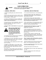
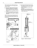
While operating, ALWAYS attach 
the clip end of the Tether Cord 
to your belt, until you dismount 
from the ATV.  The switch the 
cord is attached to will shut off 
the engine if pulled deliberately 
or by inadvertent dismount from 
the ATV seat.

DANGER 

Failure to observe the following safety instructions 
could result in serious injury and or

Summary of Contents for PB60 06

Page 1: ...INC Power Brush PB60 06 Assembly Operators Parts Manual English Language Version 06 Printed September 2006 Part 89754A 1000 6th Ave NE Portage La Prairie MB Canada R1N 3C5 www quadivator com READ SAVE THIS MANUAL ...

Page 2: ...at has been subject to alteration misuse abuse improper assembly or installation shipping damage or normal wear of the product 4 Exclusions excluded from this warranty are normal wear normal adjustments and normal maintenance In the event you have a claim under this warranty you must return the product to an authorized service dealer All transportation charges damage or loss incurred during transp...

Page 3: ...tact Information Quadivator Inc E mail mailbox quadivator com 1000 6th Ave NE Website www quadivator com Portage la Prairie MB Tel 866 770 2169 Canada R1N 3B5 Fax 204 239 4271 This symbol the industry s Safety Alert Symbol is used throughout this manual and on labels on the device itself to warn the possibility of personal injury Read these instructions carefully It is essential that you read the ...

Page 4: ...t i 2 Pre delivery Checklist iii 3 Owners Registration Delivery Checklist iv 4 Safe Operation 1 5 Setup Operation 2 Brush Mounting 2 Angle Adjustment 2 Gage Wheels 3 General Operation 3 Storage 3 Maintenance 3 6 Replacement Parts 5 7 Warranty Registration 17 Serial Number Location ...

Page 5: ...dable All fasteners are securely tight Start the Quadivator Power Brush and allow it to run for 5 10 minutes check for excessive operation or unusual noise The Quadivator Power Brush has been tested and to the best of my knowledge is ready to be delivered to the customer Date Pre delivered Signature To help prevent personal injury from thrown objects never walk or stand in the front area of the br...

Page 6: ...Quad Power Brush Operators Manual Version 06 iv OWNER S REGISTRATION DELIVERY Checklist 0 1 2 1 ...

Page 7: ... After striking a foreign object stop the engine motor remove the wire from the spark plug thoroughly inspect the brush for any damage and repair damage before restarting and operating the brush 4 If the unit should start to vibrate abnormally stop the engine motor and check immediately for the cause Vibration is generally a warning of trouble 5 Stop the engine motor whenever you leave the operati...

Page 8: ... from hitting the ATV when winch is reeled in Depending on winch location on the ATV a higher lift is required to use the second link but only if it cannot interfere with the ATV when lifted ii ANGLE ADJUSTMENT Manual Remove Pivot stop pin shown in Fig 3 2 and manually adjust angle by rotating brush to desired angle and reinsert pin Electrical Pivot Option An electrical pivot option is available a...

Page 9: ... better sweep b A level brush lasts longer c The faster the ground speed the faster the brush will wear d More aggressive brush down pressure will reduce brush life 5 Drive at low speed 6 When climbing curbs or loading brush on trailer raise brush to maximum height and drive slowly The bristles might come in contact with curb or trailer ramp STORAGE 1 Keep all nuts bolts and screws properly tighte...

Page 10: ...igure 3 2 and replace belt See Figure 3 7 Belt Drive Schematic NOTE As the engine is moved rearward on the power unit the spring loaded idler pulley under the gearbox of the Power Brush will come under greater tension Figure 3 6 7 Servicing the roller chain that drives the rotor a To replace the roller chain remove the bolts that hold the springs on the idler Remove springs Figure 3 6 b Find the c...

Page 11: ... contact information at the beginning of the manual When ordering parts please have the following information on hand Part Number you are looking for Model Number and Serial Number of the machine Quantity required To ensure warranty support for your Quadivator please fill out the Warranty Registration Card located at back of the Operator s Manual Power Brush Sub assemblies Electrical Brush Pivot O...

Page 12: ...ds and Sub Assemblies 9 12 43 45 26 52 59 35 Rear SubAssembly See Pages 8 9 Rotor Sub Assembly See pages 10 11 Front Sub Assembly See pages 12 13 54 53 52 59 32 Operators Manual Version 06 Quad Power Brush 6 ...

Page 13: ...er Mount 32 1 89909 Shield Belt Rubber 33 1 89910 Chain Assy Lift 34 1 89935 Weld t Idler Pivot 35 2 QRP 313x2 30 Pin Quick Release 36 3 LW 313 Lockwasher 5 16 37 4 HB 375x1 25 Hex Head Bolt 3 8 16 X 1 1 4 38 1 HB 375x1 5 Hex Head Bolt 3 8 16 X 1 1 2 39 4 RP 125x1 Roll Pin 1 8 x 1 40 2 FW 313 Flat Washer 5 16 Std 41 2 HB 313x 75 Hex Head Bolt 5 16 18 X 3 4 42 8 CB 375x1 Carriage Bolt 3 8 x 1 43 14...

Page 14: ...57 3 2 51 32 16 21 40 45 57 46 50 1 25 26 19 10 44 51 22 11 54 52 13 18 9 57 51 33 17 4 8 59 53 56 51 51 45 46 50 5 44 Refer to page 16 for parts breakdown of the gearbox Gearbox Assembly Quad Power Brush Operators Manual Version 06 8 ...

Page 15: ...9855A Assy Gage Wheel Optional 31 1 89860 Stud Bolt 3 8 16 NC x 80 32 2 89863 Latch 33 2 89865 Spring Comp 625 OD x 2 75FL x 054Wire 34 2 89887 Idler Sprocket 50 Pitch x 13t 17mm ID 35 2 89889 Bracket Tensioner Mount 36 1 89909 Shield Belt Rubber 37 1 89910 Chain Assy Lift 38 1 89935 Weld t Idler Pivot 39 15 CB 25x3 4 Carriage Bolt 1 4 x 3 4 40 10 CB 313x3 4 Carriage Bolt 5 16 x 3 4 41 8 CB 375x1 ...

Page 16: ...ush Operators Manual Version 06 10 53 2 34 2 SCALE 2 15 DETAIL A 23 44 5 60 44 1 43 40 Some components hidden for clarity View from Rear Some components hidden for clarity 27 37 28 42 49 36 7 44 31 44 2 34 2 42 35 44 48 5 View from Front Brush Assembly ...

Page 17: ...9855A Assy Gage Wheel Optional 31 1 89860 Stud Bolt 3 8 16 NC x 80 32 2 89863 Latch 33 2 89865 Spring Comp 625 OD x 2 75FL x 054Wire 34 2 89887 Idler Sprocket 50 Pitch x 13t 17mm ID 35 2 89889 Bracket Tensioner Mount 36 1 89909 Shield Belt Rubber 37 1 89910 Chain Assy Lift 38 1 89935 Weld t Idler Pivot 39 15 CB 25x3 4 Carriage Bolt 1 4 x 3 4 40 10 CB 313x3 4 Carriage Bolt 5 16 x 3 4 41 8 CB 375x1 ...

Page 18: ...ck Nut 3 8 NC Unitorque 10 6 FW 375 Flat Washer 3 8 Std 11 6 HB 375x1 Hex Head Bolt 3 8 16 X 1 12 6 HN 375 Hex Nut 3 8 16 UNC 13 6 LW 375 Lockwasher 3 8 ITEM 89855A QTY PART DESCRIPTION 1 2 88540 Spacer Bushing 2 1 89753 Washer Caster 3 1 89765A W A Caster Wheel Mount 4 1 89775B Weld t Gage Wheel 5 1 89822 Tube Bearing Spacer Castor 6 1 89823 Assy Rubber Wheel 7 4 89824 Bearing 6003 2RS AAB 8 1 FH...

Page 19: ... 1 5 8 x 3 00 7 1 88667 Decal Mylar Overlay Frosted 8 1 89240A Weldment Inter Frame short 9 1 89245 Assembly Bumper Pad 10 1 89290 Weld t Pulley Mount Swing Arm 11 1 89315B Pulley Double Idler Weld t 4 5 8 12 1 89318 Bushing Spacer Dbl Pulley 13 2 89442 Lug Ratchet Strap Base 14 1 89523 V Belt B116 Kevlar USA 4404 15 1 89530 V Belt B133 Kevlar 7 8727 16 2 89824 Bearing 6003 2RS AAB 17 8 FHN 5 Flan...

Page 20: ...Blower Drive 6 1 88666 Decal Serial Plate Foil 1 5 8 x 3 00 7 1 88667 Decal Mylar Overlay Frosted 8 1 89245 Assembly Bumper Pad 9 1 89290 Weld t Pulley Mount Swing Arm 10 1 89315B Pulley Double Idler Weld t 4 5 8 11 1 89318 Bushing Spacer Dbl Pulley 12 1 89440 Weldment Inter Frame Long 13 2 89442 Lug Ratchet Strap Base 14 1 89545 V Belt B136 Kevlar 15 2 89824 Bearing 6003 2RS AAB 16 8 FHN 5 Flange...

Page 21: ...88665 Decal Quadivator Corp 1 75 x 8 5 4 1 88666 Decal Serial Plate Foil 1 5 8 x 3 00 5 1 88667 Decal Mylar Overlay Frosted 6 1 89543A Decal Warning General 7 1 89879 Decal PB60 8 2 89881 Decal Amber reflective Tape 51 x 51 9 2 89882 Decal Amber reflective Tape 51 x 51 10 1 SW404 Decal Moving Part Hazard Operators Manual Version 06 Decal Locations Power Brush Quad Power Brush 15 ...

Page 22: ...Operators Manual Version 06 Quad Power Brush 16 ...

Page 23: ...6 WARRANTY REGISTRATION Quadivator PB60 Power Brush Please fax this sheet to 204 239 4271 or mail it to Quadivator Inc P O Box 1127 1000 6th Ave NE Portage la Prairie Manitoba R1N 3C5 CANADA Power Brush Model Power Brush Serial Purchased by Name Address City State Prov Mail Code Dealer Date Purchased D M Y Thank you ...

Page 24: ...Quad Power Brush _____________________________________________________________________ Operators Manual Version 06 18 ...

Page 25: ...SCRIPTION 1 1 86031 Actuator 4 Stroke HD 12VDC 17 1 2 1 86348 Instructions Power Brush Elect Pivot Kit 3 1 89906 Bracket Actuator Base 4 1 89915 Weld t Actuator Rod End 5 1 89921 Bracket Lift Extension 6 1 89930 Assy Brush Pivot Switch 7 2 CB 25x3 4 Carriage Bolt 1 4 x 3 4 8 1 CTP 125x1 Cotter Pin 1 8 x 1 9 4 FHN 25 Flange Lock Nut 1 4 NC Unitorque 10 3 FW 5N Flat Washer 1 2 SAE 11 2 HB 25x 75 Hex...

Page 26: ...er hole on the shroud where you just removed the bolt from 6 Re install bolt securing lift extension bracket to shroud using a 9 32 drill bit Drill 2 holes in the shroud flange and two holes in the existing lift pin mount bracket 7 Install 1 4 x 3 4 hex bolts in the rear locations and secure with 1 4 flange nuts Use 1 4 x 3 4 carriage bolts in the front location 8 Bolt the actuator rod mount brack...

Page 27: ...rness along the left side of the cargo box toward the front of the box 5 Route the wiring harness through the 1 2 inch 13mm hole Plug the red wire and black wire connectors to either of the center terminals of the switch Plug the red white wire and black white wire connectors to the remaining terminals of the switch Secure with ties as needed 6 Use the supplied clamp for the switch to secure the s...

Page 28: ...arness away from moving parts and pinch points 3 Locate switch and wiring harness at a convenient location so it can be worked easily Clamp switch Plug the red wire and black wire connectors to either of two center terminals on the switch Plug the red white wire and black white wire into remaing two terminals Secure wiring harness with ties as needed NOTE Tighten clamp along with the actuator swit...

Reviews: