


[ ] T1, T2 – bi-filler wound on T37-43 ferrite core
(black).
•
Cut 6” length of each color magnet wire
•
The two wires can be lightly twisted
together, but this is not necessary
•
Wind 5 turns on the core as shown.
•
Trim and tin the wire ends.
Either
scrape or melt the insulation using a hot iron with a blob
of solder.
•
Orientate the common wire ends so they are
opposite each other on the core.
•
The wires will now be in the proper position for
inserting into the board.
Be sure to tin the wire ends before installing. The transceiver will not work if you do
not tin the magnet wire. This is the leading cause of failure.
[ ] Stick the rubber bumper feet on the corners of the board.
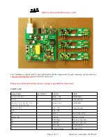
Assembling the band modules
[ ] Before populating with components,
mark each module with the band and mode in the space
provided with a permanent marker
.
[ ] J5,J6 – 5 pin right angle SIP header strip. Short 90° pins go into board. Mount on the top of the
board as shown. Trim the pins flush on the backside.
Use the placement graphic and tables below to install the capacitors, crystals, and inductors.
Note: When reading module capacitor values, do not confuse the manufacturing codes
with the component value. If it looks strange, it may be a manufacturing code, look on
the other side of the component.
Page 6 of 13
digital_txcvr_assembly_030720.pdf


