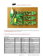


Assembly:
The first step is to sort the parts into groups of similar types. This will make finding the needed part
type and value quicker.
Start with the resistors:
Caution: Several of the values have very similar color codes and differ only by the zero
multiplier color. It is also easy to mix up the 51 and 1 Meg resistors as 51 is
green/black/brown and 1 meg is brown/black/green. L4 is a RF choke. It looks like a
resistor, but is a bit fatter. With an ohm meter, it will read 0 ohms.
[ ] R1 - 51
Green/Brown/Black/Gold
[ ] R2 - 4.7K
Yellow/Violet/Red/Gold
[ ] R3 - 1 Meg
Brown/Black/Green/Gold
[ ] R4, R6 - 100K
Brown/Black/Yellow/Gold
[ ] R5, R14, R16 - 1K Brown/Black/Red/Gold
[ ] R7, R17 - 5.6 ohm Green/Blue/Gold/Gold
[ ] R8, R10, R13 – 10K Brown/Black/Orange/Gold
[ ] R9 – 470K
Yellow/Violet/Yellow/Gold
[ ] R11 – 680K
Blue/Gray/Yellow/Gold
[ ] R12 – 47K
Yellow/Violet/Orange/Gold
[ ] R15 - 470
Yellow/Violet/Brown/Gold
[ ] L4 – 10 uH inductor Brown/Black/Black/Gold,
last band can be silver
[ ] D1 – 1N5817 Diode, black plastic body,
match band with outline
[ ] D2, D3, D4 – 1N4148 Diode, glass body, match
band with outline
Capacitors:
[ ] C1, C2, C10, C16 – 10 nF, 103 Orange highlight
[ ] C19 – 1 nF, 102 Red highlight
[ ] All others 100 nF, 104 – Yellow highlight 12 places
[ ] C12, C17, C20 – 1 uF – long lead is plus.
[ ] C3, C6- 100 uF – long lead is plus.
Note: When reading capacitor values, do not
confuse the manufacturing codes with the
component value. If it looks strange it may be
a manufacturing code, look on the other side of
the component. Also, the value may be
followed by a tolerance code - M,K, or J.
Page 4 of 13
digital_txcvr_assembly_030720.pdf


