Note:
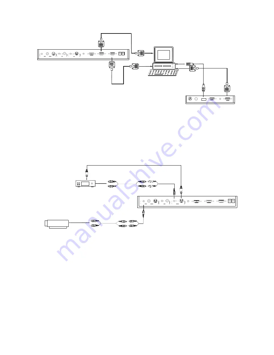
You can connect a laptop computer to the RGB IN port of side
panel with a RGB cable.
Step 4: Connect to the first video equipment with S-Video input.
RS232
Cable
MIC
PROJECTOR
Computer
USB
RGB IN
AUDIO IN
RS232
Side Panel
RGB Output
To the
Monitor
USB Connector
AUDIO IN
OUT
AUDIO VIDEO
OUT
VIDEO
AUDIO
S-VIDEO
IN
S-VIDEO
AUDIO
IN
PROJECTOR
OUT -COMPUTER- IN
OUT-12V- IN
Rear Panel
Output of the S-Video signal from the visualizer to the projector is
already done in the step 2, where the RGB cable comes out from the
visualizer and goes to the projector. After the connections as steps 2,
3, 4 are made, input signals from the computer
、
visualizer CCD and
S-Video are going to the RGB1 input on the projector and will be
displayed on the projector screen as RGB1. These signals can be
seen in turn when pressing “CCD/PC1/PC2” and “S-VIDEO/VIDEO”
on the control panel of the visualizer.
AUDIO
IN
S-VIDEO
OUT
OUT
VIDEO
AUDIO
VIDEO
Video equipment
S-Video out
Audio out
Audio input
(or amplifier/speaker equipment)
Projector
S-Video Cable
S-VIDEO
AUDIO
IN
PROJECTOR
Rear Panel
AUDIO IN
OUT-12V- IN
OUT -COMPUTER- IN
Remarks:
RGB IN signal can not go to S-VIDEO OUT or VIDEO
OUT port to be displayed on the screen.
9


