

Diagnostics/Troubleshooting
Power-On Self Test Diagnostics
4-2
59268-00 A
S
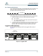
Input Power LED Is Extinguished
The Input Power LED illuminates to indicate that the switch logic circuitry is
receiving proper voltages. If the Input Power LED is extinguished, do the
following:
1.
Inspect the power cords and connectors. Is the cord unplugged? Is the cord
or connector damaged?
Yes - Make necessary corrections or repairs. If the condition remains,
continue.
No - Continue.
2.
Inspect the AC power source. Is the power source delivering the proper
voltage?
Yes - Contact your authorized maintenance provider.
No - Make the necessary repairs. If the condition remains, contact your
authorized maintenance provider.
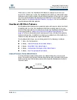
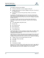
System Fault LED Is Illuminated
The System Fault LED illuminates to indicate that a fault exists in the switch
firmware or hardware. If the System Fault LED illuminates, check the Heartbeat
LED for an error blink pattern and take the necessary actions. Refer to
“Heartbeat
LED Blink Patterns” on page 4-3
.
Power-On Self Test Diagnostics
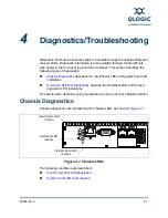
The switch performs a series of tests as part of its power-up procedure. The
POST diagnostic program performs the following tests:
Checksum tests on the boot firmware in Programmable Read Only Memory
(PROM) and the switch firmware in flash memory
Internal data loopback test on all ports
Access and integrity test on the Application Specific Integrated Circuit
(ASIC)
During the POST, the switch logs any errors encountered. Some POST errors are
critical, others are not. The switch uses the Heartbeat LED and the Logged-In
LED to indicate switch and port status. A critical error disables the switch so that it
will not operate. A non-critical error allows the switch to operate, but disables the
ports that have errors. If two or more ports fail the POST, the entire switch is
disabled. Whether the problem is critical or not, contact your authorized
maintenance provider.
Summary of Contents for SANbox 3810
Page 1: ...59268 00 A SANbox 3810 Fibre Channel Switch Installation Guide Firmware Version 7 4...
Page 8: ...viii 59268 00 A SANbox 3810 Fibre Channel Switch Installation Guide S Notes...
Page 34: ...General Description Switch Management 1 10 59268 00 A S Notes...
Page 44: ...Planning Fabric Management 2 10 59268 00 A S Notes...
Page 62: ...Installation Installing Firmware 3 18 59268 00 A S Notes...
Page 90: ...SANbox 3810 Fibre Channel Switch Installation Guide Index 6 59268 00 A S Notes...
Page 91: ......


