General Description
Chassis Controls and LEDs
1-2
59268-00 A
S
The switch is managed with the Command Line Interface (CLI) or the QuickTools
web applet.
Refer to
SANbox 3810 Fibre Channel Switch Command Line Interface
Guide
for more information about the CLI.
Refer to the
SANbox 3810 QuickTools Switch Management User Guide
for
information about QuickTools.
Chassis Controls and LEDs
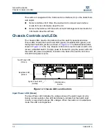
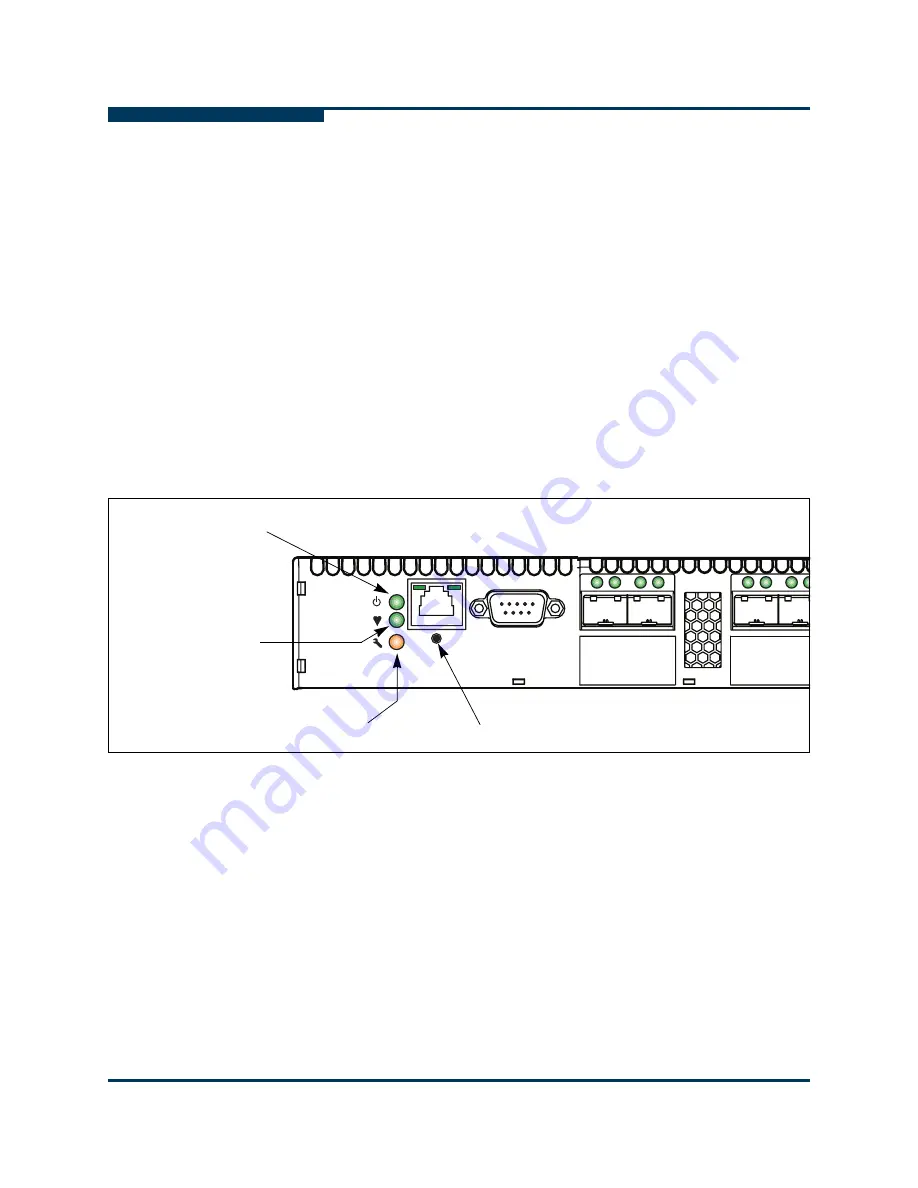
The chassis LEDs provide information about the switch’s operational status.
These LEDs include the Input Power LED (green), Heartbeat LED (green), and
the System Fault LED (amber) as shown in
Figure 1-2
. The Maintenance button
shown in
Figure 1-2
is the only chassis control and is used to reset a switch or to
recover a disabled switch. To apply power to the switch, plug the power cords into
the switch AC power receptacles, located on the back of the switch, and into a
100–240 VAC power source.
Figure 1-2 Chassis LEDs and Controls
Input Power LED (Green)
The Input Power LED indicates the voltage status at the switch logic circuitry.
During normal operation, this LED illuminates to indicate that the switch logic
circuitry is receiving the proper DC voltages. When the switch is in maintenance
mode, this LED is extinguished.
Maintenance
Button
Input Power LED
(Green)
Heartbeat LED
(Green)
System Fault LED
(Amber)
Summary of Contents for SANbox 3810
Page 1: ...59268 00 A SANbox 3810 Fibre Channel Switch Installation Guide Firmware Version 7 4...
Page 8: ...viii 59268 00 A SANbox 3810 Fibre Channel Switch Installation Guide S Notes...
Page 34: ...General Description Switch Management 1 10 59268 00 A S Notes...
Page 44: ...Planning Fabric Management 2 10 59268 00 A S Notes...
Page 62: ...Installation Installing Firmware 3 18 59268 00 A S Notes...
Page 90: ...SANbox 3810 Fibre Channel Switch Installation Guide Index 6 59268 00 A S Notes...
Page 91: ......


