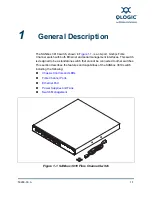
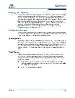

General Description
Serial Port
59268-00 A
1-7
A
Serial Port
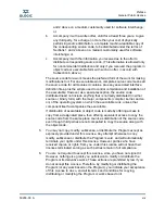
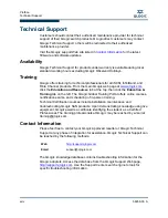
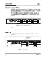
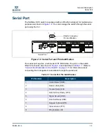
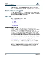
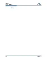
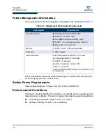
The SANbox 3810 switch is equipped with an RS-232 serial port for maintenance
purposes as shown in
Figure 1-6
. You can manage the switch through the serial
port using the CLI.
Figure 1-6 Serial Port and Pin Identification
The serial port requires a null-modem F/F DB9 cable. The pins on the switch
RS-232 connector are shown in
Figure 1-6
and identified in
Table 1-1
. Refer to
“Connect the Workstation to the Switch” on page 3-11
for information about
connecting the management workstation through the serial port.
Table 1-1. Serial Port Pin Identification
Pin Number
Description
1
Carrier Detect (DCD)
2
Receive Data (RxD)
3
Transmit Data (TxD)
4
Data Terminal Ready (DTR)
5
Signal Ground (GND)
6
Data Set Ready (DSR)
7
Request to Send (RTS)
8
Clear to Send (CTS)
9
Ring Indicator (RI)
1
5
6
9
RS-232 Connector
Pin Identification
Serial Port
Summary of Contents for SANbox 3810
Page 1: ...59268 00 A SANbox 3810 Fibre Channel Switch Installation Guide Firmware Version 7 4...
Page 8: ...viii 59268 00 A SANbox 3810 Fibre Channel Switch Installation Guide S Notes...
Page 34: ...General Description Switch Management 1 10 59268 00 A S Notes...
Page 44: ...Planning Fabric Management 2 10 59268 00 A S Notes...
Page 62: ...Installation Installing Firmware 3 18 59268 00 A S Notes...
Page 90: ...SANbox 3810 Fibre Channel Switch Installation Guide Index 6 59268 00 A S Notes...
Page 91: ......


