


24
1.9 Test card
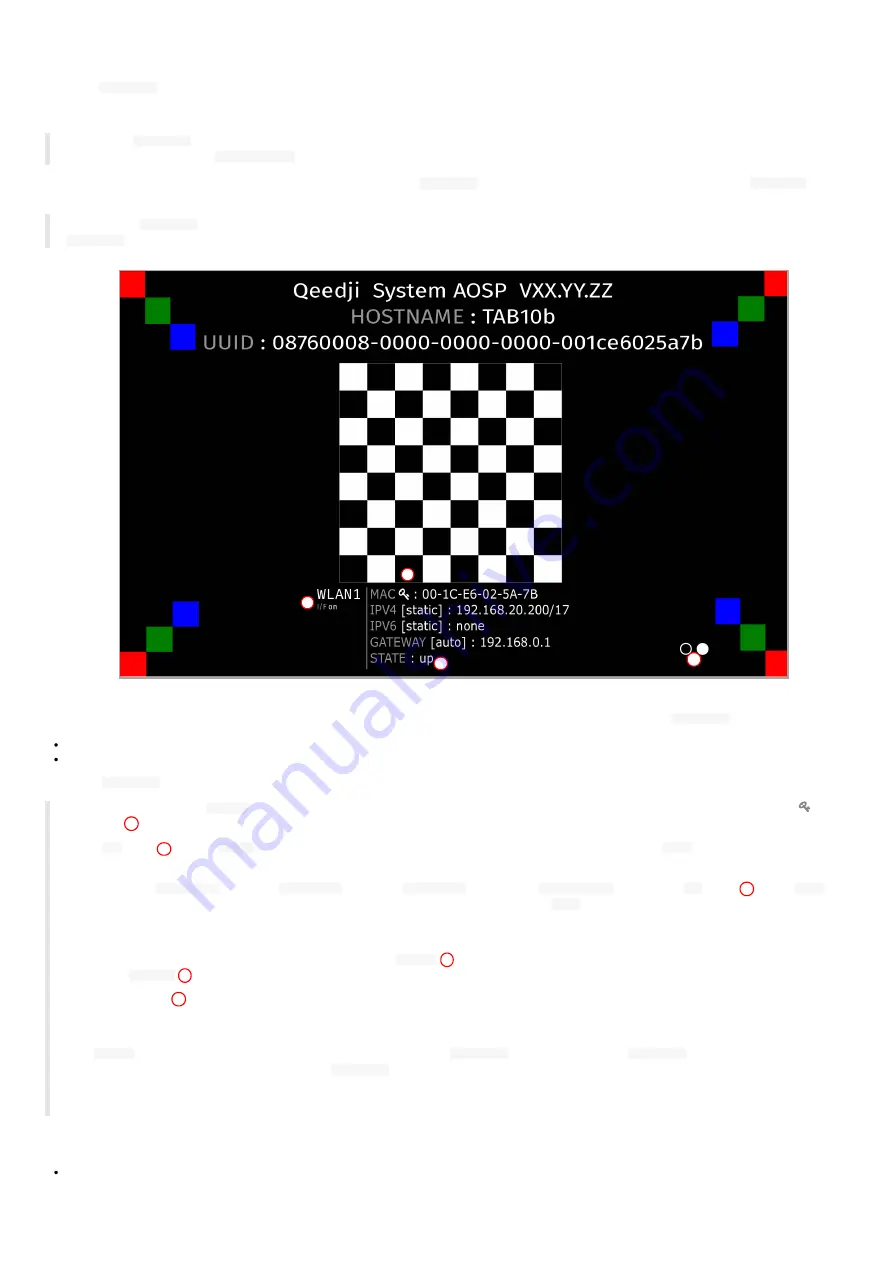
When the
Test card
App launching at device start-up is activated, the device displays alternatively one test pattern content per network interface
supported by the device every ten seconds and this for one minute. The test pattern displays important information to assist in the device
configuration.
☛
When the
Test card
App is executed at device start-up for one minute, the other App cannot be executed and the user cannot access to AQS
desktop by pressing on the
system button
.
On a TAB10b device, the test pattern content is displayed thanks to a
Test Card
App that is launched at device start-up when the
Test card
is
activated in the device configuration Web user interface.
◬
When the
Test Card
App must be executed, no other App can be executed. To execute successfully another App, your must deactivated the
Test Card
App in the device configuration Web user interface.
If you are using a
NAPOE109ku
adapter, a
NAPOE109kt
adapter, a
NAPOE109ft
adapter or a
PoE to USB-C
adapter, the
Test card
displays in alternance:
the test pattern content for the
LAN1
network interface for ten seconds,
the test pattern content for the
WLAN1
network interface for ten seconds.
If not, the
Test card
displays only the test pattern content for the
WLAN1
network interface.
☛
For TAB10b devices, the
MAC Id
value is the MAC address value of the WLAN interface. It is identified in the test pattern content by the
key
pictogram
☛
The
up
STATE
*on the
WLAN1
network interface means that the device is connected to a WIFI router. The
down
STATE means that the
device is not connected to a WIFI router.
☛
When using a
NAPOE109kt
adapter, a
NAPOE109ft
adapter, a
NAPOE109ft
adapter or a
PoE to USB-C
adapter, the
up
STATE
on the
LAN1
network interface means that the adapter is able to provide the network connectivity. The
down
STATE means that the adapter is not able to
provide the network connectivity due to either a wrong installation of the TAB10b device on the wall-mount or due to a wire crimping trouble on
the krone connector
.
☛
Only one network interface can be activated at a time. The
I/F on
status means that the current interface displayed is kept activated by
the OS; the
I/F off
status means that the current network interface (or I/F) displayed has been deactivated by the OS.
☛
The white circles
are filled with a white dot from the left to the right, each time a test pattern content for a new network interface is
displayed. When there is one LAN1 interface and one WLAN1 interface supported by the device, two white circles are displayed: the left one for the
LAN1 interface, the right one for the WLAN1 interface.
☛
In
native
mode, when navigating in the Android Settings App, if the
Test card
App was running, the
Test card
App is stopped. To relaunch
it, you can either restart the device or launch the
Test card
App available in the Android Apps view.
☛
If you have a USB keyboard plug on a USB hub connected to the TAB10b device, you can activate/deactivate the Test Card with the key
sequence
If an USB keyboard is connected to an USB hub connected to the TAB10b device, the test card content can be displayed or undisplayed by pressing this
keys sequence:
[left, right, left, right] in less than ten seconds.
The test card can be displayed/undisplayed by applying the key sequence after having plugged an USB keyboard on the USB connector of the TAB10b
device. In this case, only this user preference needs to be set to
true
:
1
2
3
4
Summary of Contents for TAB10b
Page 1: ...User manual TAB10b 9 10 18 001A TAB10b 8 30...
Page 5: ...5 Part I Description and installation...
Page 10: ...10 1 3 1 Device dimensions...
Page 13: ...13...
Page 26: ...26 Part II System con guration...
Page 42: ...42 This message is then displayed until the device is rebooting automatically once...
Page 50: ...50 Part III Applicative user interface...
Page 52: ...52 Part IV Administration console user interface...
Page 63: ...63...
Page 95: ...95 Part V Technical information...
Page 99: ...99 5 3 Antenna return loss This is the return loss diagram for the WIFI Bluetooth antenna...
Page 101: ...101 Part VI Contacts...
Page 103: ...103 Part VII Appendix...


