6
1.2 Getting started
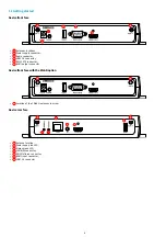
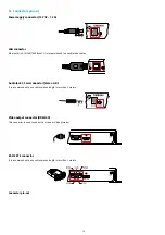
Device front face
Antennas locations,
Power supply connector,
Audio connector,
USB 2 3.0 connector,
RS232 DTE connector,
H DMI output connector.
Device front face with the WLAN option
Location of the 2 WLAN antennas to screw.
Device rear face
Antenna location,
Power supply red LED,
Status green LED,
LAN RJ 45 connector,
GPIO/Infrared connector,
H DMI input connector,
USB 1 2.0 connector.
1
2
3
4
5
6
1
1
1
7
8
9
10
11
12
13
7
Summary of Contents for 4.13.15 002E
Page 1: ...U ser manual DMB 400 4 13 15 002E...
Page 4: ...4 Part I Description and installation...
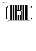
Page 7: ...7 1 2 1 Device xture...
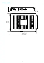
Page 8: ...8 1 2 2 Device dimensions...
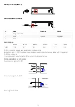
Page 15: ...15 N Function 1 CD 2 RX D 3 TX D 4 DTR 5 GND 6 DSR 7 RTS 8 CTS 9...
Page 17: ...17...
Page 19: ...19 Part II Applicative user interface...
Page 21: ...21 Part III Administration console user interface...
Page 49: ...49 Part IV Con guration b y script...
Page 51: ...51 Part V Technical information...
Page 55: ...55 Part VI Contacts...
Page 57: ...57 Part VII Appendix...
Page 62: ...62 15 16 17...


