16
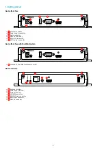
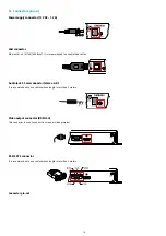
Video input connector (HDMI 1.4)
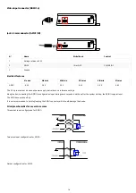
Jack 3.5 mm connector (GPIO1/IR)
N°
Name
Write/Read
Control
1
Voltage reference 3.3 V
2
GPIO1
IN or OUT
CPU/GPIO1
3
Ground
Electrical features
Vin min
Vin max
VOH min
VOL max
VIH min
VIL max
GPIO1
-0.5 V
3.6 V
2.9 V
0.4 V
2.0 V
0.8 V
The 3.3 V pin must not be used as power supply, but rather as a reference voltage.
Along the device booting, the GPIO1 is configured as input during some seconds. And then after the system startup, the GPIO1 is operational.
The GPIO has a weak pull-up.
It is not recommended to hotplug/unplug the GPIO1 connector, which could damage the device.
Principle schematics for several use cases
Three wires input configuration for GPIO1:
Two wires input configuration for GPIO1:
Output configuration for GPIO1:
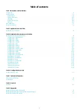
Summary of Contents for 4.13.15 002E
Page 1: ...U ser manual DMB 400 4 13 15 002E...
Page 4: ...4 Part I Description and installation...
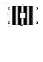
Page 7: ...7 1 2 1 Device xture...
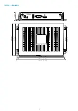
Page 8: ...8 1 2 2 Device dimensions...
Page 15: ...15 N Function 1 CD 2 RX D 3 TX D 4 DTR 5 GND 6 DSR 7 RTS 8 CTS 9...
Page 17: ...17...
Page 19: ...19 Part II Applicative user interface...
Page 21: ...21 Part III Administration console user interface...
Page 49: ...49 Part IV Con guration b y script...
Page 51: ...51 Part V Technical information...
Page 55: ...55 Part VI Contacts...
Page 57: ...57 Part VII Appendix...
Page 62: ...62 15 16 17...


