PL-LA Series User Manual
Two-Way Passive Installation Line Arrays and Subwoofer
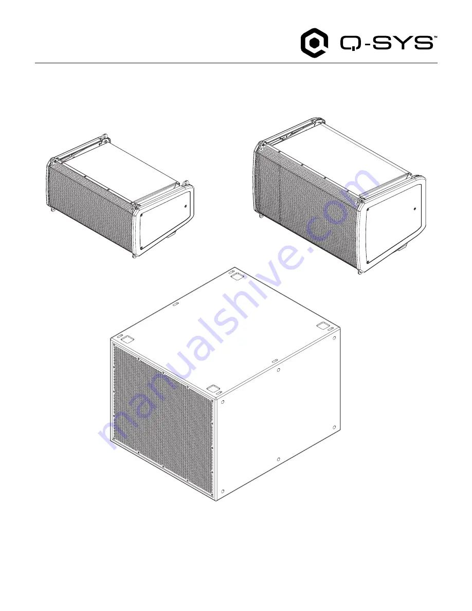
PL-LA8
PL-LA12
PL-SUB18
TD-001680-01-A
*TD-001680-01*
Page 1: ...PL LA Series User Manual Two Way Passive Installation Line Arrays and Subwoofer PL LA8 PL LA12 PL SUB18 TD 001680 01 A TD 001680 01...
Page 2: ...gging Safety Precaution 12 General Rules for Suspension 12 Shock Loading 12 Rigging Categories 12 Array Restrictions 13 Maximum Suspended Load 13 PL LA8 and PL LA12 Deployment Options 14 Ground Deploy...
Page 3: ...ment 28 Pick Point Deployment 29 Single Pick Point Deployment 29 Dual Pick Point Deployment 29 Bridle Deployment 29 Adjusting the Tilt Angle of the Array on a Pick Point Deployment 29 PL SUB18 Cardioi...
Page 4: ...rtant to use proper lifting techniques Suggested reading OSHA Technical Manual OTM Back Disorders and Injuries https www osha gov otm 1 Read follow and keep these instructions 2 Heed all warnings 3 Cl...
Page 5: ...rials of the part is above the relevant threshold specified in GB T 26572 Replacement and reduction of content cannot be achieved currently because of the technical or economic reason Rigging Safety R...
Page 6: ...a bass reflex enclosure Weatherized IP54 ABS enclosure for indoor and protected outdoor environments PL SUB18 18 inch 4 inch voice coil subwoofer in bass reflex enclosure Superior acoustic performance...
Page 7: ...ront Bottom 5 7 4 8 3 2 6 1 Figure 1 1 ABS enclosure 2 Weatherized steel grille 3 Rear panel input cup 4 M10 pull back point 5 Dual angle 35 mm pole socket 0 or 7 5 6 Removable side panel 7 Slip resis...
Page 8: ...ront Bottom 5 7 4 8 3 2 6 1 Figure 2 1 ABS enclosure 2 Weatherized steel grille 3 Rear panel input cup 4 M10 pull back point 5 Dual angle 35 mm pole socket 0 or 7 5 6 Removable side panel 7 Slip resis...
Page 9: ...1 5 4 5 8 12 angles Array Frame connection FLY and parking 2 Fastener Location for 0 5 angle 3 Fastener Location for 3 angle 4 Fastener Location for 6 10 angles 5 Angle Selection 6 Slider for angle s...
Page 10: ...Location for 1 5 4 5 8 12 angles and parking 2 Fastener Location for 0 5 3 6 angles 3 Angle selection 4 Locking 10 angle and Array Frame connection FLY 5 Slider for angle selection 6 Four attachment p...
Page 11: ...eel grille 3 Slip resistant feet 4 Rear panel input cup and Working Load Limit WLL indication 5 Integrated Rigging System PL LA8 PB Pull Back Bar PL LA12 PB Pull Back Bar WLL indication WLL indication...
Page 12: ...of the assembly Discard any worn defective or suspect parts and replace them with new appropriately load rated parts Shock Loading When a load is moved or stopped its static weight is magnified Sudde...
Page 13: ...ted component weights The tabulated Working Load Limits represent static loads only Dynamic and shock load conditions are determined by unknown installation specific factors The choice of which Safety...
Page 14: ...9 For Stacked on an Array Frame see page 19 For Stacked on a PL SUB18 see page 16 Flown Deployment PL LA12 options shown For Flown Deployment with an Array Frame see page 23 For Attaching PL LA to PL...
Page 15: ...surfaces level materials vibrations wind etc to deploy the loudspeakers in a stable and safe manner Use additional measures to secure the loudspeaker pole not included when necessary PL LA8 Loudspeake...
Page 16: ...to deploy the loudspeakers in a stable and safe manner Use additional measures to secure the subwoofer not included when necessary PL LA12 Loudspeaker An array of up to three 3 PL LA12 loudspeakers c...
Page 17: ...SUB18 1 Attach two Straight Links to the middle slots of the PL SUB18 do not torque yet 2 Place the second PL SUB18 on top of the first PL SUB18 3 Torque to 1 1 3 N m 100 lbf in with the bolts provide...
Page 18: ...e On the 0 5 the down tilt angle will be 12 5 NOTE Using the two extreme holes of the link will result in a shift of 5 up up tilt of 5 on the FLY position 0 when in the 8 position and down tilt of 7 5...
Page 19: ...as a stand alone loudspeaker the integrated lower feet of the PL LA8 PL LA12 line array loudspeakers ensure that the enclosure remains exactly perpendicular to the stage floor making it ideal for fron...
Page 20: ...tion resistant locking feature Locking feature reusability is not affected by the number of uses WARNING Always use the Q SYS SC 000777 01 M6 shoulder screws provided with the rigging system Attaching...
Page 21: ...up tilt of the frame you can reverse the Array Frame and attach the front of the Loudspeaker at the point labeled 5 in Figure 17 and the Rear link at the point labeled 6 in Figure 17 In this configur...
Page 22: ...oudspeakers 1 Attach the front of the PL LA to the next PL LA loudspeaker 2 Select the desired angle 3 Attach slider at the back ATTACH point 4 Insert a screw into the corresponding locking hole 5 Rep...
Page 23: ...ct Y Links on the array frame Two links at the front and two links in the middle NOTE The nut side of the Y Link will always be placed to the inside of the array 2 Insert the links into the PL SUB18 3...
Page 24: ...he nut side of the Y Link will always be placed to the inside 3 Attach the front of the loudspeaker to the Straight Link labeled 1 in Figure 17 4 Attach the back of the loudspeaker slider bar in posit...
Page 25: ...ttachment 2 Attach the link from the top of the bottom PL SUB18 into the base of the top PL SUB18 3 Torque the four bolts to 1 1 3 N m 100 lbf in to ensure that the bottom PL SUB18 is correctly fasten...
Page 26: ...avity alone Pullback Bar Deployment The Pullback Bar can be used in two use cases 1 When gravity alone does not allow reaching the desired down tilt angle the Pullback Bar can be used on the rear of t...
Page 27: ...olt can be used on the rear of the lowest loudspeaker of small arrays to provide another pick point for further support to angle the system WARNING Do not exceed the Working Load Limits of the M10 Pul...
Page 28: ...lly For a heavier array or when the array is deployed by a single person you can use a ratchet strap between the array frame and the M10 Pullback Point of the last loudspeaker 3 Change your angles to...
Page 29: ...5 8 in shackles not included can be attached to the two outer rails of the Array Frame at the CG point for the desired angle NOTE Use EASE Focus 3 available online to locate the CG point and desired v...
Page 30: ...the same gain on each one Refer to the Q SYS online documentation There are three Cardioid configurations Back to back Stacked flown in the array or ground stacked Side by side Back to Back Placing t...
Page 31: ...gement and Fake Grille For applications where cosmetic appeal is important you can install another grille on the back of the rear facing PL SUB18 In that case the Rear Panel Connection won t be access...
Page 32: ...th ends The speakON NL4 connector offers 4 poles and accommodates wire up to 10 AWG 6 mm Refer to Neutrik TM instructions for assembling Euroblock Connector and speakON NL4 Connectors Passive Mode Bi...
Page 33: ...ecision between 300 and 800 Hz The exact model will depend on your application the number of loudspeakers per channel and the type of loudspeaker The number in parenthesis means that it may work but w...
Page 34: ...wiring harness plug into the desired mode receptacle at the bottom of the cup 5 Turn the input cup over and verify that yellow is visible in the proper SETTING port If not move the plug into the desi...
Page 35: ...d While the grille is protected by a mesh that avoids ingress of water into the port it is recommended to angle the loudspeaker with a down tilt of 5 to allow eventual creeping water to get out of the...
Page 36: ...36...
Page 37: ...S website for Technical Support and Customer Care including their phone numbers and hours of operation qsys com contact us Warranty For a copy of the QSC Limited Warranty go to qsys com support warran...