s.r.l.
pompe per vuoto
EU 105 - EU 105/B
13
6.2 Sostituzione olio
Sostituire l'olio lubrificante effettuando l'operazione a pompa calda.
ATTENZIONE:
Utilizzare guanti protettivi per evitare scottature.
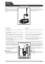
Con riferimento alla figura 6, svitare il tappo di carico (A) e quello di
scarico olio (C) solo dopo aver posizionato sotto il serbatoio un con-
tenitore adatto (per forma e dimensioni) a raccogliere tutto l'olio della
pompa; quando l'olio esausto contenuto nel serbatoio sarà fuoriuscito
rimontare i tappi ("A" e "C") e far girare la pompa sotto vuoto per
circa un minuto in modo da svuotare anche il circuito di lubrificazio-
ne/raffreddamento dai residui dell'olio esausto, quindi togliere i tappi
e scaricare la rimanenza d'olio.
Se nell'olio sono presenti grosse quantità di sostanze inquinanti o si
riscontra la presenza di acqua, procedere ad un lavaggio della pompa
facendola funzionare a vuoto massimo con circa 1 litro di olio pulito
per almeno 5 minuti. Scaricare nuovamente l'olio.
Procedere quindi al nuovo riempimento d'olio (Vedi "messa in servizio"
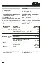
e "tabella olii consigliati").
6.3 Sostituzione elemento elastico del giunto
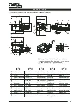
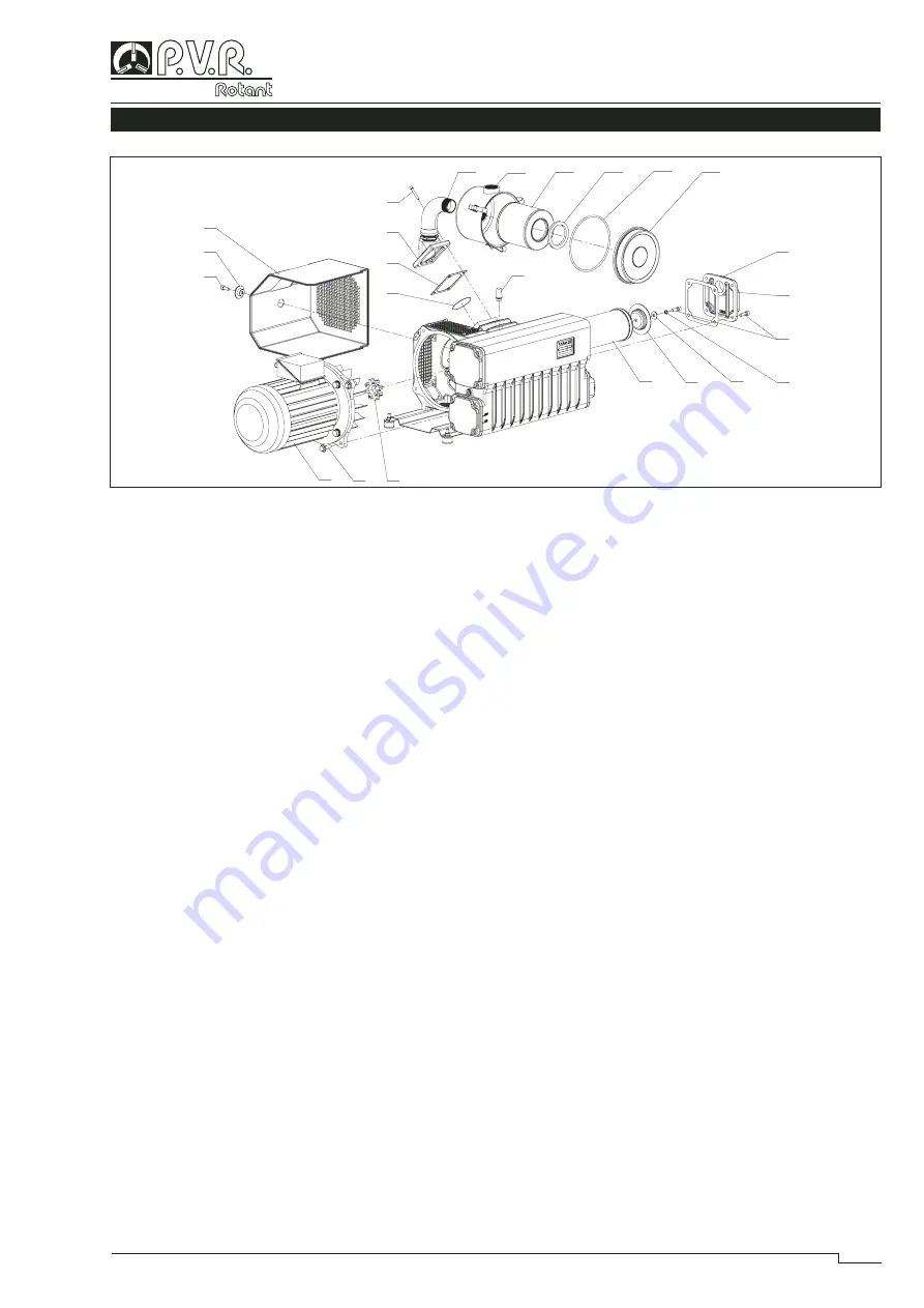
(Vedi Fig.7)
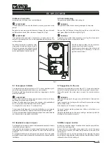
Staccare l'assieme motore (pos.95) togliendo le viti (pos.55) e verifi-
care lo stato dell'elemento elastico (pos.17), se necessario sostituirlo.
Rimontare avvitando le viti.
AVVERTENZE:
Il funzionamento con l'elemento elastico del giunto rovinato provoca
una rumorosità anomala della pompa soprattutto in fase di accensione
e può portare alla rottura del giunto e dell'albero della pompa.
6.4 Sostituzione elemento disoliatore
(Vedi Fig.7)
Elementi disoliatori molto sporchi possono causare un sensibile au-
mento di temperatura della pompa e in casi estremi autocombustione
dell'olio lubrificante.
La massima pressione ammessa nel serbatoio è di 0,6 bar misurata a
portata massima (quando la pompa sta funzionando con l'aspirazione
a pressione atmosferica).
Se è presente il manometro sul serbatoio verificare l'intasamento della
cartuccia a pompa calda.
Per la sostituzione togliere il coperchio (pos.40) svitando le relative
viti (pos.51).
Togliere la vite (pos.51) e sostituire l'elemento disoliatore. Se neces-
sario sostituire i due OR e la guarnizione (pos.38).
Per il montaggio procedere in senso inverso.
6.2 Oil change
Replace the lubricating oil with the pump still warmed-up.
ATTENTION:
Use protective gauntlets to avoid burnings.
Please refer to figure 6. Unscrew the oil filling plug (A) and the dischar-
ge plug (C) only after having placed below the pump tank a suitable
container (proper size and shape) for collecting the total quantity of
oil. Once the oil in tank has completely been discharged, re-assemble
both the plugs ("A " and "C") and let the pump run under vacuum
for about one minute, so that the lubricating/cooling line get emptied
and any oil residual keeps inside the pump. Then remove the plugs
and discharge the rest of oil.
If the oil is polluted or if some water is in the oil, clean the pump by
letting it run at maximum vacuum level with about 1 litre of fresh oil
for at least 5 minutes. Change again the lubricating oil.
Fill the pump with fresh oil (please see "commissioning" and "recom-
mended oil table").
6.3 Coupling elastic element replacement
(See Fig.7)
Remove the motor (pos.95) assembly unscrewing the screws (pos.55)
and check the elastic element (pos.17) conditions. If necessary, replace
it. Assemble by screwing the screws.
WARNING:
The operation with damaged elastic element causes an anomalous
pump noise, especially when starting the pump and may cause the
coupling and pump shaft breaking.
6.4 Exhaust filter replacement
(See Fig.7)
Very dirty exhaust filters may cause a considerable pump temperature
increase and in extreme cases oil lubricant spontaneous ignition.
Maximum allowed pressure in the tank is 0,6 bar measured at the
maximum capacity (when the pump is working with the inlet against
atmospheric pressure).
If there is the pressure gauge on the tank, check the element blockage
with the pump still warmed-up.
For the replacement remove the cover (pos.40) unscrewing the res-
pective screws (pos.51).
Remove the screw (pos. 51) and replace the exhaust element. If ne-
cessary replace the two O rings and the gasket (pos. 38).
For the assembly proceed the opposite way.
86
85
83
82
81
74
80
21
95
55
17
47
48
49
50
38
40
51
309
310
312
311
313
314
Fig.7

