background image

Page 6 / 15 


PV500-67  03/17


3.  COMMANDS (MESSAGES) 

Modbus standard has several commands used to access different types of data. The XR10CX only uses the data type 
called Holding Registers (40001 

– 49999) and Output Coils (00001 – 09999). There are only 3 commands needed to 

access  the  Holding  Registers,  and  2  commands  for  the  Output  Coils.  The  Modbus  specification  allow  reading  and 
writing  to  multiple  sequential  registers,  but  the  maximum  number  of  registers  that  can  be  read  or  written  to  in  one 
command is 5. The limit for reading Coils is 80 and writing coils is only 1 at a time. This is a limitation of the XR10CX 
device. In the following commands, the actual address will be used, the command indicates the type of register it is. 
For example, the first Register 40001 will have address 0 and the first Coil 00001 will also have address 0. 
 

3.1  READ OUTPUT COIL (0x01): 

Read Coils from device. Coil status will be packed into the data bytes in the response. Only requested Coil data is valid 
and the extra bits that may be present for padding the bytes should be ignored. 
 

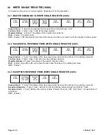
3.1.1  MASTER COMMAND TO READ COILS (0x01):  


Slave Address: 

 (1 byte): Device address that receives the command. Range: 1-247. 

Function Code: 

 (1 byte): Code = 0x01 (Read Output Coil). 

Coil Address: 

 (2 bytes): The address of the first coil to be read, reading multiple registers is sequential. 

Number of Coils: 

 (2 bytes): Number of Elements (Coils) that the device has to return (3 = 3 Coils or bits). No more 

than 80 Elements (Coils) allowed. (Each coil is 1 bit). 

CRC: 

 (2 bytes): CRC calculated for the frame data received and is used to verify the integrity of data received. 


3.1.2  SUCCESSFUL RESPONSE, READ COILS (0x01): 


Slave Address:  

 (1 byte): The address of the slave responding. Same as the address in the initiating command. 

Function Code: 

 (1 byte): Code = 0x01 Echo from the initiating command. 

Number of Bytes: 

 (1 byte): Defines the number of bytes followed minus the CRC. 

Data: 

 Byte data buffer

, length is “Number of Bytes” long. Coil data I contained in this data. The first 8 Coils will be the 

first Byte. 

CRC: 

 (2 bytes): 


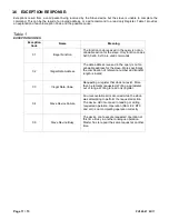
3.1.3  EXCEPTION RESPONSE, READ HOLDING REGISTER (0x01): 


Slave Address:  

 (1 byte): The address of the slave responding. Same as the address in the initiating command. 

Exception Response: 

 (1 byte): Code = 0x01 Echo from the initiating command plus high bit 0x80 = 0x81. 

Exception  Code: 

  (1  byte):  Defines  the  number  of  bytes  followed  minus  the  CRC.  See  Table  1  for  explanation  of 

exceptions. 

CRC: 

 (2 bytes): 


Slave 

Address 

Function 

Code 0x01 

Coil 

Address 

(MSByte) 

Coil 

Address 

(LSByte) 

Number of 

Coils 

(MSByte) 

Number of 

Coils 

(LSByte) 

CRC 

(LSByte) 

CRC 

(MSByte) 

Slave 

Address 

Success 

echo: 

Code 

0x01 

Number 

of 

Bytes 

Data 1 

Data 

CRC 

(LSByte) 

CRC 

(MSByte) 

Data … 

Slave 

Address 

Exception 

0x01 + 0x80 

Error: 0x81 

Exception 

Code 

see list 

CRC 

(LSByte) 


CRC 

(MSByte) 

Summary of Contents for XR10CX

Page 1: ...PV500 67 03 17 MODBUS RTU Applied to the XR10CX Control WATER HEATER DIGITAL OPERATING CONTROLLER PVI INDUSTRIES LLC Fort Worth Texas 76111 Web www pvi com Phone 1 800 433 5654 ...

Page 2: ... EXCEPTION RESPONSE READ HOLDING REGISTER 0x03 8 3 4 WRITE SINGLE REGISTER 0X06 9 3 4 1 MASTER COMMAND TO WRITE SINGLE REGISTER 0x06 9 3 4 2 SUCCESSFUL RESPONSE FROM WRITE SINGLE REGISTER 0x06 9 3 4 3 EXCEPTION RESPONSE FROM WRITE SINGLE REGISTER 0x06 9 3 5 WRITE HOLDING REGISTERS 0x10 10 3 5 1 MASTER COMMAND TO WRITE HOLDING REGISTER 0x10 10 3 5 2 SUCCESSFUL RESPONSE FROM WRITE HOLDING REGISTERS ...

Page 3: ...register list 2 1 1 DEFINITIONS MODBUS Protocol A messaging structure used for communication between devices machines sensors and or computers Modbus RTU Remote Terminal Unit Implementation of the Modbus protocol on top of a serial line with an RS 232 RS 485 or similar physical layer The XR10CX uses 2 wire RS 485 Physical Layer and implements Modbus RTU Master Device Also known as Client this devi...

Page 4: ...simply needs the 40000 added to it Setpoint ST1 is Register 769 or the actual Register Number 40769 For a list of all available registers see Table 2 Input Registers Discrete Inputs and Coils MODBUS defines several types of data The only data used by the XR10CX is the Holding Register 40001 49999 and Output Coils 00001 09999 The XR10CX does not use Input Registers or Inputs Coils CRC ERROR CHECKIN...

Page 5: ...uested by the Master 2 After sending the Slave goes back to listen mode ii If command was not successfully processed 1 Slave will respond with and exception response and exception code indicating why it was not processed a Possible caused would be invalid address See Table 1 Exception Codes 2 After sending The Slave goes back to listen mode b If the command received fails the CRC validation no res...

Page 6: ...first coil to be read reading multiple registers is sequential Number of Coils 2 bytes Number of Elements Coils that the device has to return 3 3 Coils or bits No more than 80 Elements Coils allowed Each coil is 1 bit CRC 2 bytes CRC calculated for the frame data received and is used to verify the integrity of data received 3 1 2 SUCCESSFUL RESPONSE READ COILS 0x01 Slave Address 1 byte The address...

Page 7: ... the slave responding Same as the address in the initiating command Function Code 1 byte Code 0x05 Echo from the initiating command Coil Address 2 bytes Echo from initiating command Data 2 bytes Echo from initiating command CRC 2 bytes 3 2 3 EXCEPTION RESPONSE WRITE SINGLE COIL 0x05 Slave Address 1 byte The address of the slave responding Same as the address in the initiating command Exception Res...

Page 8: ...e The address of the slave responding Same as the address in the initiating command Function Code 1 byte Code 0x03 Echo from the initiating command Number of Bytes 1 byte Defines the number of bytes followed minus the CRC Data Byte data buffer length is Number of Bytes long CRC 2 bytes 3 3 3 EXCEPTION RESPONSE READ HOLDING REGISTER 0x03 Slave Address 1 byte The address of the slave responding Same...

Page 9: ... from the initiating command Register Address 2 bytes The address of the register that was written Data 2 bytes Byte data buffer will contain the same data that was sent in initiating command CRC 2 bytes 3 4 3 EXCEPTION RESPONSE FROM WRITE SINGLE REGISTER 0x06 Slave Address 1 byte The address of the slave responding Same as the address in the initiating command Exception Response 1 byte Code 0x06 ...

Page 10: ...ONSE FROM WRITE HOLDING REGISTERS 0x10 Slave Address 1 byte The address of the slave responding Same as the address in the initiating command Function Code 1 byte Code 0x10 Echo from the initiating command Register Address 2 bytes The address of the register that was written Number Registers 2 bytes The number of registers written CRC 2 bytes 3 5 3 EXCEPTION RESPONSE FROM WRITE HOLDING REGISTERS 0...

Page 11: ...ata Address The data address received in the query is not an allowable address for the slave More specifically the combination of reference number and transfer length is invalid 03 Illegal Data Value Requesting a register that does not exist More than 5 elements requested Writing a parameter out of range Writing to read only register 04 Slave Device Failure An unrecoverable error occurred while th...

Page 12: ...up 40831 Did Read Write Dig Input Alarm Delay 0 255min 40847 Adr Read Write Modbus Address 1 247 40852 Set Read Write System Setpoint 40864 Coil Read Write On Off for Control 513 Read Write Keypad Lock 516 Read Write Mute Buz and Any Alarm 517 Read Digital input Pin 9 520 Read Probe 1 Error 521 Read Probe 2 Error 522 Read Probe 3 Error 523 Read Probe 4 Error 524 Read High Temperature Alarm Pb1 525...

Page 13: ...r burner is also ON Alarms Modbus Coil 538 Alarms are not typically used on this device CONTROL ON OFF Enable Disable Modbus Coil 513 ON 257 or 0x0101 OFF 1 or 0x0001 In the OFF state no heating signal will be present no alarms all relay outputs are open and no temperature are displayed The display will show the word OFF It is still possible to read the probe temperatures and other parameters over...

Page 14: ... 3 IMPROPER WIRING EXAMPLE Figure 5 Wiring is not correct Not a daisy chain and the master is not at an end MASTER CLIENT DEVICE 1 XR10CX DEVICE 2 XR10CX DEVICE 3 XR10CX DEVICE 4 XR10CX MASTER CLIENT DEVICE 1 XR10CX DEVICE 2 XR10CX DEVICE 3 XR10CX DEVICE 4 XR10CX Master Regis ter Addr ess LSB yte Data MSByte G N D Data LSB CRC LSByte C R T X TXD1 RXD1 DATA B R e D a Data LSByt e CRC LSByte 2 W CON...

Page 15: ...lly a jumper setting on the device The XR10CX does not have line biasing resistors Data B will be pulled to positive Data A will be pulled to negative 6 6 SERIAL INTERFACE XJ485 The XJ485 serial termination is a factory supplied RS485 to TTL connection device The XR10CX control comes standard with a TTL communication port also used as the HOT KEY programming interface The termination points are la...

Reviews: