Page 5 / 15
PV500-67 03/17
2.2.1 Normal Communication diagram
Figure 1
MODBUS Transaction (Error Free)
2.2.2 Communication with exception code
Figure 2
MODBUS Transaction (Error, Exception Code response)
2.3 SEQUENCE OF MODBUS RTU COMMAND AND RESPONSE:
1) Master (Automation System) Sends command to Slave devices (XR10CX)
2) After transmitting, the Master turns off the line driver and listens
3) All Slave Devices receives command. (They are in listen mode)
a) If address matches Slave address and the CRC is valid, that Slave will process command.
i)
If command was successfully processed
(1) Slave responds with its own slave address, and echoes the command it received, and includes any data
that may have been requested by the Master.
(2) After sending, the Slave goes back to listen mode.
ii) If command was not successfully processed
(1) Slave will respond with and exception response and exception code indicating why it was not processed.
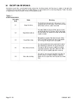
(a) Possible caused would be invalid address. See Table 1 Exception Codes
(2) After sending, The Slave goes back to listen mode.
b) If the command received fails the CRC validation, no response is given.
c) If the command received does not match the Slave address, no response is given.
d) If the command is incomplete, no response is given.
e) If no command is received, no response is given.
Initiate Request
Function Code
Data Request
Perform the action
Initiate the response
Receive the Response
Master
Slave
Initiate Request
Function Code
Data Request
Error Code
Exception Code
Error detected in the
packet, initiate an error
Receive the response
Master
Slave
Data Response
Function Code


