Page 8 / 15
PV500-67 03/17
3.3 READ HOLDING REGISTERS (0x03):
Read a single register or multiple registers from the XR10CX. Response will be the values stored in the registers.
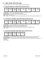
3.3.1 MASTER COMMAND TO READ REGISTERS (0x03):
Slave Address:
(1 byte): Device address that receives the command. Range: 1-247.
Function Code:
(1 byte): Code = 0x03 (Read holding register).
Register Address:
(2 bytes): The address of the first register to be read, reading multiple registers is sequential.
Number of Registers:
(2 bytes): Number of Elements (Registers) that the device has to return (3 = 3 Registers). No
more than 5 Elements (registers) allowed. (Each register is 16 bits).
CRC:
(2 bytes): CRC calculated for the frame data received and is used to verify the integrity of data received.
3.3.2 SUCCESSFUL RESPONSE, READ HOLDING REGISTERS (0x03):
Slave Address:
(1 byte): The address of the slave responding. Same as the address in the initiating command.
Function Code:
(1 byte): Code = 0x03 Echo from the initiating command.
Number of Bytes:
(1 byte): Defines the number of bytes followed minus the CRC.
Data:
Byte data buffer
, length is “Number of Bytes” long.
CRC:
(2 bytes):
3.3.3 EXCEPTION RESPONSE, READ HOLDING REGISTER (0x03):
Slave Address:
(1 byte): The address of the slave responding. Same as the address in the initiating command.
Exception Response:
(1 byte): Code = 0x03 Echo from the initiating command plus high bit 0x80 = 0x83.
Exception Code:
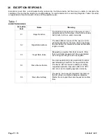
(1 byte): Defines the number of bytes followed minus the CRC. See Table 1 for explanation of
exceptions.
CRC:
(2 bytes):
Slave
Address
Function
Code 0x03
Register
Address
(MSByte)
Register
Address
(LSByte)
Number of
Registers
(MSByte)
Number of
Registers
(LSByte)
CRC
(LSByte)
CRC
(MSByte)
Slave
Address
Success
echo:
Code
0x03
Number
of
Bytes
Data 1
Data
n
CRC
(LSByte)
CRC
(MSByte)
Data …
Slave
Address
Exception
0x03 + 0x80
Error: 0x83
Exception
Code
see list
CRC
(LSByte)
CRC
(MSByte)


