


PureAire Monitoring Systems, Inc.
5/25/07
10
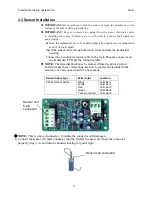
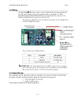
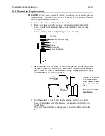
3.4 Wiring
The
Air Check
Lite
uses a single, 3-wire shielded cable for analog output and
24 VDC power input. A three-wire shielded cable (3-conductor, 18 AWG
stranded) General Cable E2203S.30.860
is recommended for the connection. The
maximum permissible cable length is 0.62 miles (1 km).
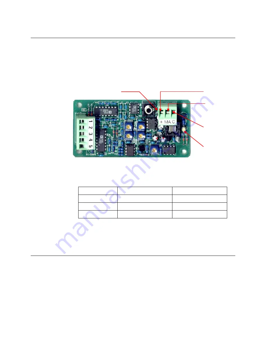
The analog out and VDC power in connections are made on the terminal block
inside the transmitter housing.
These connections are made as follows:
Pin #
Connection
Description
1
Power
DC +24V Input
2
Signal Out
4-20mA Output
3
Common (Signal Ground)
0V
IMPORTANT:
If connecting directly to a 24VDC power source, you must
use a 100-ohm resistor between pins 2 and 3 to simulate a load. Without
this resistor the Air Check
Lite
will not operate properly.
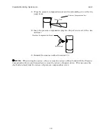
3.5 Initial Startup
Once installation of the gas detector has been completed, it is ready for startup. The following
procedures should be performed before putting the instrument into operation:
1.
Check the integrity of all wiring.
2.
Apply 24 VDC power.
The instrument should now be operating properly.
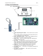
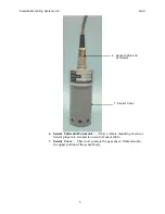
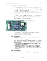
Power/Analog Out
Terminal Block
+
= 24VDC Power
MA
= 4-20mA signal
output
(connects to PLC)
C
= Common signal
ground
Green LED
is
illuminated when
24VDC power and
4-20mA are
terminated
Summary of Contents for Air Check Lite
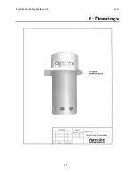
Page 26: ...PureAire Monitoring Systems Inc 5 25 07 23 6 Drawings ...
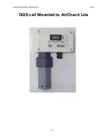
Page 28: ...PureAire Monitoring Systems Inc 5 25 07 25 DQS cell Mounted to AirCheck Lite ...
Page 29: ...PureAire Monitoring Systems Inc 5 25 07 26 Membrane ...
Page 30: ...PureAire Monitoring Systems Inc 5 25 07 27 24VDC 3 wire is remote up to 1000 meters ...


