Pumpex K 100 Starting And Operating Instructions Download Page 8

8

Inspection

Pump section

Inspection

Action in the event of a fault

Cables

Check that the sheath is not damaged. Check that the cables are not kinked or nipped.

Fit a new cable. Correct the fault

Visible parts

Check that all parts are in good condition, and that bolts

Replace worn parts. Tighten

and nuts are securely tightened.

any loose bolts and nuts.

Impeller/wear ring*

Check that the parts are not worn to such an extent that the pump performance is

1. Adjust the wear ring.

affected.

2. Fit a new impeller/wear ring.

Shaft seal

Check that the oil is clean and is not mixed with water. See under ”Changing the oil”.

In the event of slight leakage, change the oil.
In the event of major leakage, fit a new seal.

 Hoses, pipes and valves

Check that the equipment does not leak  or is otherwise damaged.

Adjust or replace defective equipment.

*= N.B. All pumps are not equipped with a wear ring.

Starting

jerk

Before starting:

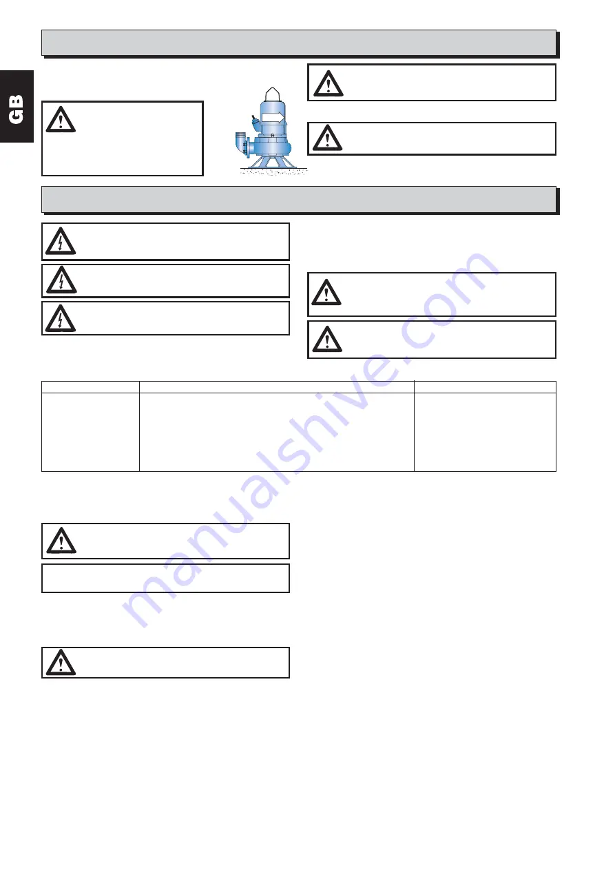
Check the direction of rotation of the pump (see
figure). At the instant of starting, the pump will jerk
anti-clockwise when viewed from above.

Changing the oil

Change of oil is done the same way on cooled and uncooled pumps.
Open oilscrews on both sides (as picture 1 on page 19).
Lean pump or only motor on the side, drain the oil into a clean receptacle.
Examine the oil.

Operation

CAUTION!
Under certain operating conditions, the pump tempera-
ture may be high.

If the direction of rotation is incorrect, transpose two phases. See under the
heading ”Electrical connections”.

CAUTION!
The starting jerk may be violent. Don’t hold the pump
handle when checking the direction of rotation. Make sure
that the pump is firmly supported and cannot rotate.

WARNING!
Never insert your hand or any
other object into the inlet opening
on the underside of the pump

casing when the pump is connected to the
power supply.
Before inspecting the pump casing, check
that the pump has been isolated from the
power supply and cannot be energized.

Service and maintenance

CAUTION!
Before any work is started, check that the pump is isolated
from the power supply and cannot be energized.

The figures within brackets are item numbers and are shown on the sectional
drawings on the fold-out pages at the end of the manual.

CAUTION!
When the pump or motor section has been laid on its side,
always secure it with wedges from both sides to prevent it
from rolling away.

CAUTION!
Before undertaking any service work, make sure that the
pump is thoroughly clean, and bear in mind the importance
of observing good personal hygiene.
Follow your local safety instructions.

Regular inspection and preventive maintenance will ensure more reliable
operation. The pump should be inspected every six months, or more often if the
operating conditions are difficult. The cable should be checked more frequently.

For a complete overhaul of the pump, please get in touch with an authorized
Pumpex workshop or your Pumpex dealer.

Lay the motor section on its side. Secure the motor section with wedges on
both sides. Check that it is securely in place and cannot roll away.
Hold the impeller to prevent it from rotating and release the impeller bolt
(see picture 3 on page 19). Remove the washer. If the impeller is stuck, tap
it gently with a lead mallet.
If the impeller is still stuck, two crowbars can be used to prise under the
impeller hub (see picture 4 on page 19).
Remove the impeller and remove the key from the shaft.

To fit

Make sure that the shaft end is clean and free from burrs. Use fine emery
cloth to rub down any damage. Fit the key. Oil the shaft end and impeller hub.
Check that the key has been correctly fitted into the keyway in the shaft. Fit
the impeller, washer and impeller bolt. Use a screwdriver or similar tool to

Fill with new oil (see table on page 18). Use White Oil with a viscosity of 20
cSt, such as BP Enerpar M002 or equivalent. Always fit a new seal washers
on the oil screws. Assemble in the reverse order.

Changing the impeller.

To remove

Remove the motor section. Drain the oil.

prevent the impeller from rotating, and tighten the bolt. Raise the motor
section. Fit the motor section to the volute. Tighten the latch bolts.
Check the clearance between the impeller and wear ring.
Adjust if necessary. See under ”Adjusting the wear ring”.

Changing the seal unit

To remove

On cooled versions cooling liquid must be drained out before changing seal
cartridge. Drain cooling liquid by removing lower plug (below cooling pipe,
see picture 2 on page 19), and remove top filling screw.
The seal cartridge can be removed as one unit without the need for special
tools. Replace the cartridge by an overhauled unit.
Drain the oil and remove the impeller. See under ”Changing the oil” and
”Changing the impeller”.
Remove the four screws retaining the seal cartridge (see picture 5 on page
19).
To press out the cartridge, screw two M6 screws (at least 40 mm long) into
the tapped holes and tighten them (see picture 6 on page 19).

To fit

Note! Dry and wet installed pumps have different seal units.
Oil the shaft and the three O-rings on the seal cartridge (two on the outside
of the seal housing and one inside the seal sleeve).
Fit the seal cartridge to the shaft. Press it carefully into place.
N.B. Don’t use a tool to apply blows to the seal cartridge.
Secure the seal cartridge by means of the four screws. Fit the impeller and
fill with oil (+ cooling liquid). See under ”Changing the oil” and ”Changing the
impeller”.

Adjusting the wear ring.

A pump with a channel impeller is equipped with an adjustable wear ring
mounted in the volute. After a period of operation or after the pump has
been dismantled, the clearance between the impeller and the wear ring
should be checked.
Lay the pump on its side. Secure the pump in position by means of wedges
on both sides. Check that the pump is firmly retained and cannot roll away.
Use a feeler gauge to measure the clearance between the wear ring and the
impeller. The clearance must not exceed 0.7 mm.
If the clearance must be adjusted, release the Allen screws in the wear ring.
Tap the wear ring lightly with a hammer or a plastic mallet until the clearance is
correct. Tighten the set screws, check that the impeller can be rotated by hand.

CAUTION!
Dismantling and repair of explosion proof motors may only
be carried out by approved personnel in specially approved
work shops.

CAUTION!
Parts must be replaced by genuine spares, including
screws, to insure correct strength in Flameproof
enclosures.

CAUTION!
In the event of inward leakage, the oil housing may be
pressurized. When removing the oil plug, hold a piece of
cloth over it to prevent oil from splashing.

NOTE!
Old oil should be entrusted to an oil disposal company in
accordance with local regulations.

CAUTION!
A worn impeller often has sharp edges. Take care not to cut
yourself on them.

Summary of Contents for K 100

Page 1: ...EEx d IIB T4 Start och driftinstruktion 2 Starting and operating instructions 6 Intriebnahme und Betriebsanleitung 10 Mise en service et utilisation 14 K 80 K 83 K 87 K 100 K 150 351914AC ...

Page 2: ...kt OIL Oljemängd COOLANT Kylvätskemängd Varvtal Vikt I Märkström Pumpen kan transporteras och lagras stående eller liggande Se till att den är säkert surrad och ej kan rulla Innehåll Dataskylt exempel Användningsområde Tillverkaren garanterar att fabriksny pump inte avger luftburet buller över 70 db A vid normal drift helt eller halvt dränkt För torruppställd pump gäller högst 75 db A Kontrollera ...

Page 3: ...s båda ändar Vid byte av kabel kontrollera följande för att undvika läckage att kabelinföringens gummibussning och brickor stämmer för kabeln Se reservdelslistan att kabelns ytterhölje inte är skadat Vid montage av kabel som tidigare använts i pumpen skall alltid gummibussningen bytas och en bit av kabeln kapas bort så att gummibussningen kommer på ett nytt ställe på kabeln Byte av kabel VARNING D...

Page 4: ...ntering Se till att axeländen är ren och fri från grader Eventuella skador putsas bort med en fin smärgelduk Montera plattkilen Olja in axeländan och pumphjulsnavet Kontrollera att plattkilen sitter rätt i spåret på axeln Montera pumphjulet Luta pumpen eller bara motorn töm oljan i rent kärl och undersök oljan Fyll ny olja se tabell sida 18 Använd vitolja med låg viskositet ca 20 cSt till exempel ...

Page 5: ...betar men ger för litet flöde Roterar pumphjulet åt rätt håll Se Drift Nej Skifta två faser se Elektrisk inkoppling Ja Är pumphus eller pumphjul igensatta Ja Rengör och kontrollera att eventuell slitring är rätt justerad Nej Är pumphjul eller eventuell slitring slitna Ja Byt slitna delar och eller justera slitringen Nej Är eventuella ventiler eller rör igensatta Ja Åtgärda fel Nej Är lyfthöjden fö...

Page 6: ...intended for pumping waste water untreated or clean water and slurries The pumps have an approval with designition Eex d IIB T4 and can be used in an explosive or flammable environment The manufacturer guarantees that a new pump will not emit airborne noise in excess of 70 dB A during normal operation when submerged or half submerged The corresponding value for the pump in a dry installation is a ...

Page 7: ...by an autorized electrician Electrical connections The power supply should be fused with slow blow fuses NOTE For safety reasons the earth conductor in the pump should be longer than the phase conductors If the motor cable is accidentally wrenched off the earth conductor should be the last to break away from its terminal This applies to both ends of the cable that the cable sheath is not damaged W...

Page 8: ...to prise under the impeller hub see picture 4 on page 19 Remove the impeller and remove the key from the shaft To fit Make sure that the shaft end is clean and free from burrs Use fine emery cloth to rub down any damage Fit the key Oil the shaft end and impeller hub Check that the key has been correctly fitted into the keyway in the shaft Fit the impeller washer and impeller bolt Use a screwdriver...

Page 9: ...e it delivers is too low Is the impeller rotating in the right No Transpose to phases See under direction See Operation Electrical connections Yes Is the volute or impeller clogged Yes Clean and check that the wear ring if any has been correctly adjusted No Is the impeller or wearring if any worn Yes Replace any worn parts and or adjust the wear ring No Are the valves or pipes clogged Yes Remedy t...

Page 10: ...ner neuen Pumpe die Luftschallemission während des normalen Betriebes ganz oder teilweise eingetaucht nicht mehr als 70 dB A beträgt Der entsprechende Wert für die Pumpe in Trockenaufstellung liegt bei maximal 75 dB A Nach längerer Lagerung muß die Pumpe kontrolliert und das Laufrad von Hand gedreht werden bevor die Pumpe in Betrieb gesetzt wird Bei der Kontrolle ist besonderes Augenmerk auf die D...

Page 11: ...üssen die Anzahl Leitungen die eventuell verwendete Anlaßvorrichtung und die Anlaßmethode siehe Typenschild bekannt sein Es gelten die folgenden Anschlußschemata ACHTUNG Die Elektroinstallation muß den nationalen und lokalen Vorschriften entsprechen ACHTUNG Alle elektrischen Anlagen müssen stets geerdet sein Dies gilt sowohl für die Pumpe als auch für etwaige Überwachungsvorrichtungen 50Hz 7 adrig...

Page 12: ...en lassen sowie die Menge und den Zustand des abgelassenen Öles prüfen In jeden Fall ist dann neues Öl gemäss der Tabelle auf Seite 18 einzufüllen Nur weissöl physiologisch unbedenklich mit geringer Viscosität ca 20 cSt ist zu vervenden wie bespielsweise BP Enerpar M002 oder ein gleichwertiges Produkt Nach jedem Öffnen der Öllochschrauben sind deren Dichtscheiben zu ersetzen Einbau Darauf achten d...

Page 13: ...äuft aber die Förderleistung ist zu niedrig Stimmt die Drehrichtung des Laufrads Nein Zwei Phasen vertauschen Siehe Abschnitt Elektroanschluß siehe Betrieb Ja Ist das Pumpengehäuse oder das Laufrad Ja Reinigen und kontrollieren ob der Verschleißring falls vorhanden verstopft korrekt eingestellt ist Nein Ist das Laufrad oder der Verschleißring falls Ja Verschlissene Teile austauschen und oder vorha...

Page 14: ...e l eau propre et la boue La pompe est conçue et approuvée suivant EEx d IIB T4 et peut être utilisée en atmosphère explosive ou inflammable La pompe peut être transportée et stockée en position verticale ou horizontale Veiller à ce qu elle ne risque pas de basculer ou de rouler Sommaire Plaque signalétique exemple Manipulation ATTENTION Contrôler l état de la poignée de levage et le serrage de se...

Page 15: ...es rondelles de l entrée de câble correspondent au diamètre du câble voir liste des pièces de rechange que la gaine extérieure du câble n est pas endommagée En cas de réutilisation du même câble sur une pompe il faut toujours remplacer la bague en caoutchouc et couper un morceau du câble pour que la nouvelle bague ne soit pas en contact avec la même partie du câble que précédemment ATTENTION Un câ...

Page 16: ...us fréquents En ce qui concerne les révisions complètes veuillez vous adresser à un atelier Pumpex agréé ou au distributeur Pumpex Certaines pompes ne sont pas munuies d un anneau d usure Remplacement de l huile Le remplacement de l huile s effectue de la même manière sur les pompes refroidies et non refroidies Ouvrir les bouchons des 2 côtés voir figure 1 page 19 ATTENTION Il peut régner une cert...

Page 17: ... tourne t elle dans le sens correct Non Permuter deux phases voir Branchement électrique Voir Fonctionnement Oui La volute ou la roue est elle bouchée Oui Nettoyer et contrôler le réglage de l anneau d usure si la pompe en est équipée Non La roue est elle usée ou l anneau d usure si Oui Remplacer les pièces usées et ou régler l anneau d usure la pompe en est équipée Non Y a t il un bouchage de van...

Page 18: ... 129 131 35 36 150 152 K 100 4 5 1 1410 16 9 2 7 4 10x1 5 2 2 0 45 0 3 2 127 134 36 65 142 144 K 100 6 7 3 1430 23 13 10 4 10x1 5 2 2 0 45 0 3 2 134 141 36 65 150 152 K 150 4 5 1 1410 16 9 2 7 4 10x1 5 2 2 0 45 0 3 2 146 65 150 152 K 150 6 7 3 1430 23 13 10 4 10x1 5 2 2 0 45 0 3 2 154 65 158 160 K 150 2 7 3 7 933 15 7 4 5 9 10x1 5 2 2 0 45 0 3 2 146 65 150 152 Without with cooling jacket Coolant 7...

Page 19: ...19 1 2 3 4 5 6 7 8 ...

Page 20: ...20 Thermal switches Leakage sensor 351850 AB Thermal switches Leakage sensor 351849 AB Thermal switches Leakage sensor 351855 AB Ä Y 50 Hz 1 2 351850 AA 351849 AA 3 Ä 351855 AA Y ...

Page 21: ...21 ...

Page 22: ...22 ...

Page 23: ...eisen van de EG richtlijn 73 23 93 68 89 392 91 368 89 336 89 106 EEC EEG m b t veiligheid en gezondheid Ex overeenkomstig 94 9 EEC som denne erklæring vedrører overholder de grundlæggende sikkerheds og sundhedskrav i EF direktiv 73 23 93 68 89 392 91 368 89 336 89 106 EEC EØF Ex er i overensstemmelse med 94 9 EEC a que se refere esta declaraçao corresponde às exigencias fundamentais respectivas à...

Page 24: ...EX AB P O Box 5207 Tel 46 8 725 49 30 Rökerigatan 20 Fax 46 8 659 33 14 SE 12118 JOHANNESHOV SWEDEN E mail info pumpex com www pumpex com Tillverkaren förbehåller sig rätten att ändra utförande och specifikationer EX 57 0409 Int DIGITAL Pumpex AB ...

Reviews: