Page 42 of 52
11.3
Priming of Leak Detection Diaphragm
IF THE LEAK DETECTION SYSTEM IS OPENED TO THE ATMOSPHERE DURING
MAINTENANCE OR INSPECTION, THE SYSTEM MUST BE RE-PRIMED PROPERLY TO
AVOID DIAPHRAGM DAMAGE AND ENSURE PROPER LEAK DETECTION OPERATION AND
SYSTEM PERFORMANCE.
THE STANDARD FACTORY INTERMEDIATE FLUID IS A SILICON OIL. IF ANY OTHER
CUSTOMER SPECIFIED MEDIA IS USED, IT MUST BE COMPATIBLE WITH THE MATERIALS
OF CONSTRUCTION.
1. Complete re-assembly of the diaphragm, reagent
head, and external components. Ensure that the
reagent head and tie bar bolts are tightened
according to the appropriate torque specifications
(Appendix IV).
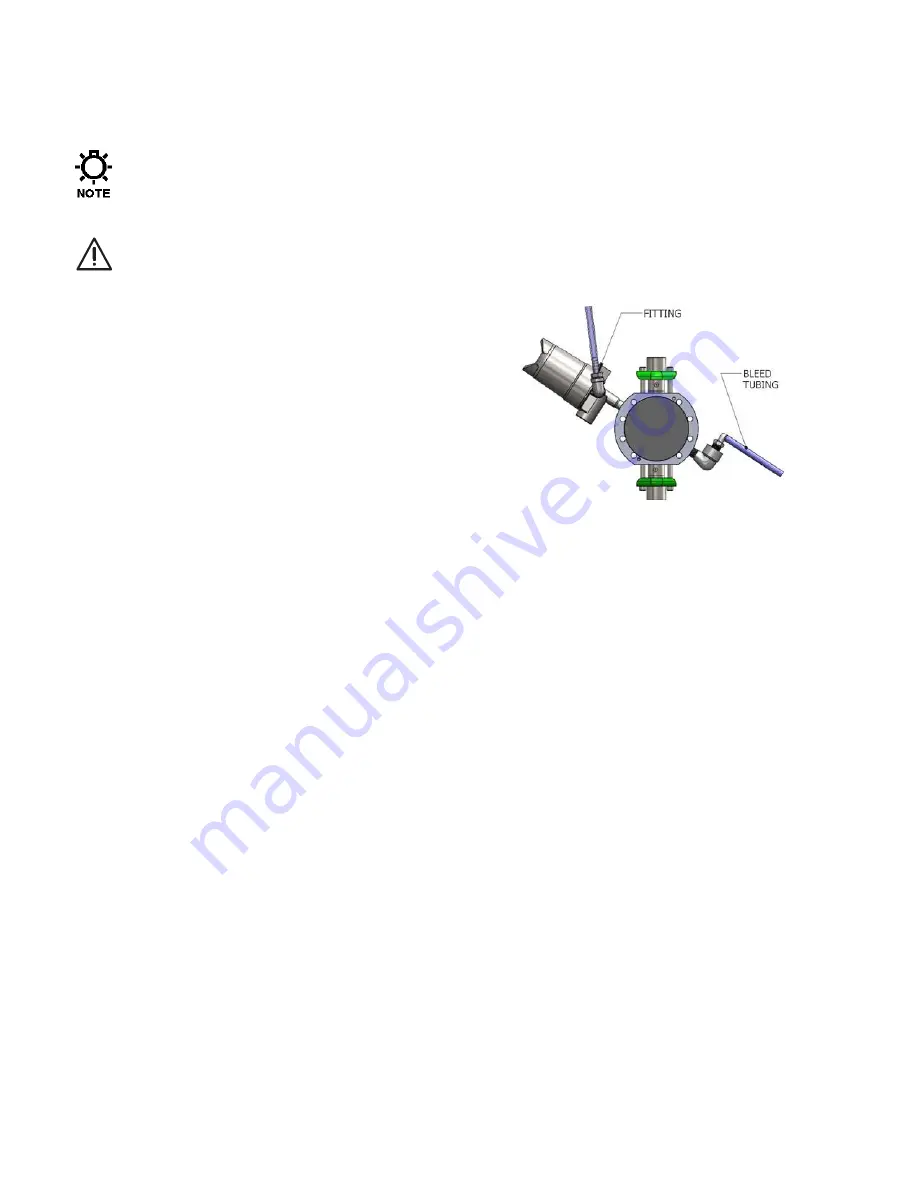
2. Remove the pressure gauge from the housing body
and replace with the straight tubing connection that
is supplied with the pump.
3. Install a short length of the appropriately sized tubing
to the fitting and connect a vacuum supply (either
handheld or electric vacuum pump).
4. Remove the pipe plug from the fill port and install the
90º fitting supplied with the pump.
5. Install a short length of the appropriately sized tubing to the fitting and place tube into the
container of the barrier fluid being used.
6. Apply a vacuum, the fluid should rise into the fill tube and enter through the system.
7. Observe the fluid at the exit (vacuum pump) side. When clear, air free fluid is observed, close
the fill valve, while maintaining the vacuum on the system for approximately 2 -3 minutes to
begin the process of drawing out excess fluid.
8. Remove the vacuum source and leave the tube on the outlet side (pressure gauge) open to
atmosphere.
9. If the pump is not already hydraulically primed, remove the PTP valve from the top of the pump
head. Using a plastic funnel or similar, slowly pour hydraulic fluid into the pump head cavity
until full.
10. Inspect the PTP valve to ensure the sealing O-ring is still in position and re-install the valve.
11. Adjust the pump to full (100%) stroke.
12. To fully balance and evacuate the leak detection system, the pump must now run at normal
discharge pressure for a period of about thirty minutes to one hour.
13. Supply either process fluid, or test fluid (i.e. water) to the suction fitting and ensure that the
discharge system is configured for safe operation. The pump can be started with minimal
discharge pressure and then slowly brought up to full pressure, if the system allows for this.
14. Apply power and start the pump. Hold down the PTP valve momentarily and observe the port
via sight glass. Continue to depress the PTP to release any entrapped air within the hydraulics
until you observe oil from the sight glass.
15. Slowly increase the discharge pressure to full operating pressure and continue to run the pump
for a period of one hour.
16. During this time, excess barrier fluid will be displaced from the system into the short length of
the tubing attached to the exit port, balancing the system for proper operation. A small pen
mark on the tube can assist in observing this process visually.
17. After the one-hour startup period, remove the tubing and connection from the housing body and
reinstall the pressure gauge.
18. Reconnect the alarm to the external system if necessary.
19. The pump and pressure leak detection system are now properly prepared and ready for normal
service. During normal operation, the gauge should indicate zero (0) pressure.


