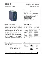


CT10.241, CT10.241-C1
CT-Series
3-P
HASE
,
24V,
10A,
240W
May 2018 / Rev. 2.0a DS-CT10.241-EN All values are typical figures specified at 3x 400Vac, 50Hz input voltage, symmetrical
phase voltages, 24V, 10A output load, 25°C ambient and after a 5 minutes run-in time unless otherwise noted.
www.pulspower.com Phone +49 89 9278 0 Germany
7/28
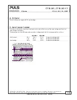
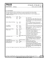
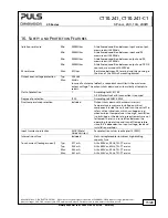
6.
DC
O
UTPUT
The output provides a SELV/PELV rated voltage, which is galvanically isolated from the input voltage.
The device is designed to supply any kind of loads, including unlimited capacitive and inductive loads.
The output is electronically protected against overload, no-load and short-circuits. In case of a protection event,
audible noise may occur.
Output voltage
Nom.
24V
Adjustment range
Min.
24-28V
Guaranteed value
Max.
30V
This is the maximum output voltage which can occur
at the clockwise end position of the potentiometer
due to tolerances. It is not a guaranteed value which
can be achieved.
Factory setting output voltage
Typ.
24.1V
±0.2% in “single use” mode at full load, cold unit
Typ.
24.1V
±0.2% in “parallel use” mode at 10A, cold unit
(results to 23.9V ±0.7% at 12A and 25.0V ±0.2% at no
load)
Line regulation
Max.
10mV
Between 3x 323 and 3x 576Vac input voltage change
Load regulation
Max.
100mV
Between 0 and 10A in “single use” mode, static value
Typ.
1000mV
Between 0 and 10A in “parallel use” mode, static
value, see Fig. 6-2
Ripple and noise voltage
Max.
50mVpp
Bandwidth 20Hz to 20MHz, 50Ohm
Output current
Nom.
12A
1)
At 24V and an ambient temperature below 45°C
Nom.
10A
At 24V and 60°C ambient temperature
Nom.
7.5A
At 24V and 70°C ambient temperature
Nom.
10.3A
1)
At 28V and an ambient temperature below 45°C
Nom.
8.6A
At 28V and 60°C ambient temperature
Nom.
6.5A
At 28V and 70°C ambient temperature
Reduce output current linearly b45°C and +70°C
Fuse breaking current
Typ.
23A
Up to 20ms once every five seconds, see Fig. 6-1.
The fuse braking current is an enhanced transient
current which helps to trip fuses on faulty output
branches. The output voltage stays above 20V.
Overload behavior
Continuous current See Fig. 6-1
Overload/ short-circuit current
Max.
23A
Continuous current, see Fig. 6-1
Output capacitance
Typ.
6 500µF
Included inside the power supply
Back-feeding loads
Max.
35V
The unit is resistant and does not show
malfunctioning when a load feeds back voltage to
the power supply. It does not matter whether the
power supply is on or off. The absorbing energy can
be calculated according to the built-in large sized
output capacitor.
1) This current is also available for temperatures up to +70°C with a duty cycle of 10% and/ or not longer than 1 minute every 10 minutes.