


CT10.241, CT10.241-C1
CT-Series
3-P
HASE
,
24V,
10A,
240W
May 2018 / Rev. 2.0a DS-CT10.241-EN All values are typical figures specified at 3x 400Vac, 50Hz input voltage, symmetrical
phase voltages, 24V, 10A output load, 25°C ambient and after a 5 minutes run-in time unless otherwise noted.
www.pulspower.com Phone +49 89 9278 0 Germany
24/28
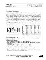
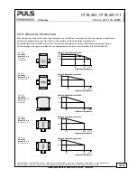
22.4.
S
ERIES
O
PERATION
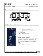
Devices of the same type can be connected in series for higher output
voltages. It is possible to connect as many units in series as needed, providing
the sum of the output voltage does not exceed 150Vdc. Voltages with a
potential above 60Vdc must be installed with a protection against touching.
Avoid return voltage (e.g. from a decelerating motor or battery) which is
applied to the output terminals.
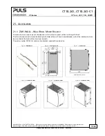
Keep an installation clearance of 15mm (left / right) between two power
supplies and avoid installing the power supplies on top of each other. Do
not use power supplies in series in mounting orientations other than the
standard mounting orientation.
Pay attention that leakage current, EMI, inrush current, harmonics will increase when using multiple devices.
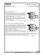
22.5.
P
ARALLEL
U
SE TO
I
NCREASE
O
UTPUT
P
OWER
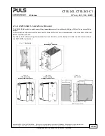
Devices can be paralleled to increase the output power. The output voltage
of all devices shall be adjusted to the same value (±100mV) in “Single Use”
mode with the same load conditions on all units, or the units can be left
with the factory settings. After the adjustments, set the unit to “Parallel
Use” mode, in order to achieve load sharing. The “Parallel Use” mode
regulates the output voltage in such a manner that the voltage at no load is
approx. 4% higher than at nominal load.
The ambient temperature is not allowed to 60°C.
If more than three units are connected in parallel, a fuse or circuit breaker
with a rating of 15A or 16A is required on each output. Alternatively, a diode or redundancy module can also be
utilized.
Keep an installation clearance of 15mm (left / right) between two devices and avoid installing devices on top of each
other. Do not use devices in parallel in mounting orientations other than the standard mounting orientation or in any
other condition where a reduction of the output current is required (e.g. altitude).
Pay attention that leakage current, EMI, inrush current, harmonics will increase when using multiple devices.
Unit B
-
+
Load
+
-
AC
DC
AC
DC
-
+
Unit A
Unit B
-
+
Load
+
-
AC
DC
AC
DC
-
+
Unit A