33
3.3.1 THE
SPEEDS
Your furnace is equipped with a 4-speed blower. Using the pellet central processing unit (Pellet CPU), we have
created 6 functional speeds. Refer to Table 2 below for the various speed configurations.
Table 2 – The Speeds
Speed
Corresponding data
CFM*
STATIC PRESSURE
1
Blower speed #1 using 90V
400 0.2’’
W.C.
2
Blower speed #1 using 115V
700 0.2’’
W.C.
3
Blower speed #2 using 98V
775 0.2’’
W.C.
4
Blower speed #2 using 115V
875 0.2’’
W.C.
5
Blower speed #3 using 115V
1075 0.2’’
W.C.
6
Blower speed #4 using 115V
1175 0.2’’
W.C.
*These results were measured at exit of plenum during laboratory tests. Results may vary depending of the
configuration and installation.
3.3.2 THE
WALL
THERMOSTAT
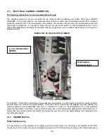
You must connect your pellet central processing unit (Pellet CPU) to a wall thermostat. If your furnace is equipped
with an auxiliary electrical heating option, you must have two wall thermostats. The main thermostat must be
connected to the “WOOD MECH” port on the pellet central processing unit (Pellet CPU). The electric option’s
thermostat must be connected to the “USER MECH” port on the pellet central processing unit (Pellet CPU). The
“WOOD24VAC” & “USER24VAC” ports are only necessary when connecting an external appliance that shares the
furnace blower (example : AC, heat pump).
3.3.3 SYSTEM
BALANCING
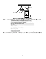
It is important to call upon a professional installer for the installation of the furnace and the ducting system
configuration. Certain check-ups must be performed and certain rules must be respected in order not to damage the
blower. When all components are installed on the furnace and the ducting system is connected to the various rooms
of the house, you must balance the ducting system. In order to do so, start the furnace blower by selecting the
recirculation mode (CIRC). Then, in the FAN section, use the arrows to select speed #4 (refer to Table 2). It is
important to respect the velocity in the main duct, the secondary ducts, as well as the velocity at the room outlets.
The static pressure of your system must be adjusted to at least 0.2 IN.W.C. and must not exceed 0.5 IN.W.C.
Finally, make sure that you never exceed the maximum blower current. Velocity in the main duct should reach at
least 700 fpm.
3.3.4 HEAT MODE (AUTOMATIC HEATING)
Operation
When the temperature in your house is below the value at which your wall thermostat is programmed, a signal is
sent to your furnace through the pellet central processing unit (Pellet CPU), activating the maximum pellet feed rate.
The RTD temperature probe, located inside the hot air plenum of your furnace, reads the plenum temperature
continuously. When the temperature reaches the start-up value (KIP –
Kick-in Point
), the distribution blower starts
functioning at the minimum speed. Thereafter, the blower increments its speed until it reaches the best efficiency
point (BEP) determined by the manufacturer. If the temperature inside the hot air plenum exceeds the limit
determined by the manufacturer, the blower automatically selects the maximal speed in order to cool off the furnace
Summary of Contents for CADDY ALTERNA
Page 11: ...11 A B C Step 2 Remove the screws around the blower assembly...
Page 49: ...49 6 GENERAL WIRING DIAGRAM...
Page 50: ...50...
Page 51: ...51...

