


Lynx.GX Installation and Management
Chapter 2. Installing the IDU and RFU
The following sections describe how to install the GX radios.
▪
Step 1. Gather Required Tools (below)
▪
Step 2. Unpack the Remaining Contents of Shipping Box (on page 9)
▪
Step 3. Test the Radios Back-to-Back (on page 11)
▪
Step 4. Install the Radio Units (on page 14)
▪
Step 5. Install and Adjust the Antenna (on page 18)
▪
Step 6. Establish Connections (on page 22)
▪
Step 7. Adjust Output Power (on page 27)
▪
Step 8. Establish a Link Between the Radios (on page 28)
▪
Step 9. Establish near-end to far-end Communications Using Orderwire (optional) (on page 31)
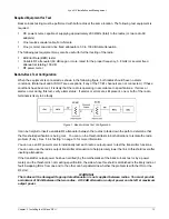
STEP 1. GATHER REQUIRED TOOLS
The following sections list the tools required when installing the radios.
IDU Installation Tools (Indoor)
You must obtain the following tools before installing the IDU:
▪
Phillips (cross-tip) screwdrivers (for 19-inch rack-mounting and attachment of brackets)
▪
Small blade (1/8”) standard screwdriver (for power supply connector)
▪
Wire crimpers (if using any 8-pin modular 2-wire or 4-wire connectors that are not pre-made)
▪
Soldering iron (if using any D-type connector)
▪
Adjustable 6” wrench to attach the chassis ground wire (
7
/
16
” for RFU and ¼” for IDU)
No additional tools are required from the above list if the RFU is mounted indoors.
RF Unit Installation Tools (Outdoor)
You must obtain the following before installing the RF Unit outdoors:
▪
RFU outdoor mounting kit (NOT INCLUDED WITH SHIPMENT; order separately)
▪
Adjustable 6-inch wrench (for installing the mounting bolts)
▪
Large blade standard screwdriver (for pole mounting clamps)
▪
Additional weatherproofing material for sealing the IDU and antenna connectors. (Butyl tape supplied with
RFU mounting kit.)
Test and Configuration Tools
The following tools, which are necessary and useful to have available for testing and configuring the radios:
Digital Multi Meter..................................................... To measure RSL, DC power, and for antenna alignment
RF power meter........................................................ To measure transmitter output power.
Cellular telephone or 2-way radio............................. For talking with far-end crew and tower crew.
Bit Error Rate test set ............................................... To test link after installation.
Computer* ............................................................... For NMS access.
Pair of touch-tone telephones 1.4 B or less REN ..... To test Orderwire circuits and for communication with far-end.
*with 10/100 Ethernet Network Interface Card, CAT5 cross-over cable, and Internet browser
Chapter 2. Installing the IDU and RFU
8


