12
L
OCAL OPERATION ON
THE FRONT PANEL
E Operating Manual with Troubleshooting Guide
www.protecta.hu
Activate button
- Activates the selected parameter set so the device will use those values. The
activated parameter set will have a red box around it. Only devices configured with multiple
parameter sets have an activate button. Note: if the parameterset change has a condition
configured to it, the activation button will disappear. In this case, activation of the parameter sets
is defined in the device configuration (e.g. binary input or software switch).
Edit button
- This button takes the user to another screen listing the available function blocks
(FBs).
The screen in Figure 3-6 will only appear if there are more than one parameter sets. Otherwise,
the user is immediately taken to the function blocks. Normally, the various function blocks appear
in blue. In case someone has changed a certain value within a given function block, the name of
the function block in this menu item will turn red to notify the user. Within function blocks, the
values of the parameters are normally green, but if they have been modified, they will also turn
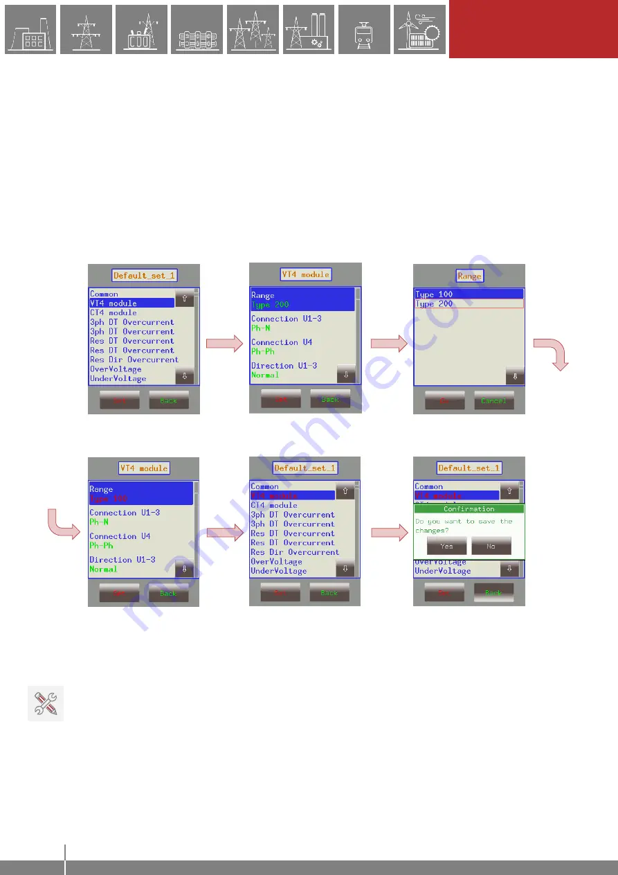
red. As an example, change the VT4 voltage type from 200V to 100V as follows:
“Set” function block
“Set” parameter
“Ok” for new value
“Back” to FB
“Back” to save data
“Yes” to confirm changes
Figure 3-7 Changing VT4 module Type
IMPORTANT! In order to finalize all changes, the user has to go back to the screen where all the
function blocks are listed and save the changes as shown above.
Also, make sure that while someone is modifying the parameters in the LCD touchscreen, another
person is not doing so on the web interface since this could lead to confusion as to what the
values of a parameter set are.


