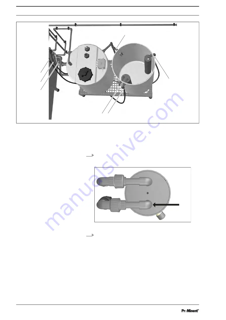
ProMinent DULCOLyse Original Operating Instructions Download Page 28

2
1

3

1 2

3

B0956

4

Fig. 17: Couplings
1. Coupling for "Brine softener" hose, transparent

2. "Brine membrane cell" PE coupling, blue

3. "Fill brine tank" PE coupling, red

4. "Brine tank overflow" coupling

28. Use the black PE hose (Ø16 mm x 1.8 mm) from the brine

tank to join the "Fill brine tank" connector (3) on the system

to the Ø16 mm connector on the brine tank.

Fig. 18: "Brine membrane cell" connector
29. Use the (Ø16 mm x 1.8 mm) PE hose to join the "Brine mem‐

brane cell" connector on the system to the Ø16 mm con‐

nector on the brine tank.

Installation and assembly


28

Summary of Contents for DULCOLyse

Page 1: ...rating instructions 2006 42 EC 985179 BA DZ 008 06 21 EN Please carefully read these operating instructions before use Do not discard The operator shall be liable for any damage caused by installation or operating errors The latest version of the operating instructions are available on our homepage ...

Page 2: ...formation includes detailed descriptions of the haz ardous situation see Ä Chapter 2 1 Labelling of Warning Informa tion on page 9 The following symbols are used to highlight instructions links lists results and other elements in this document Tab 1 More symbols Symbol Description Action step by step Outcome of an action Links to elements or sections of these instructions or other applicable docum...

Page 3: ...inciples 35 6 4 Other settings 35 6 5 Manual operation 36 7 Commissioning 37 7 1 Check list Preparation for commissioning 37 7 2 Check list Commissioning 40 7 3 Commissioning work 42 8 ALARM Troubleshooting menu 51 8 1 Status messages 51 8 2 Error messages 52 8 2 1 Vacuum system 52 8 2 2 Power supply 53 8 2 3 Caustic tank 53 8 2 4 Product tank 54 8 2 5 Separating tank 55 8 2 6 Booster pump 55 8 2 ...

Page 4: ...on in n F B n Brewery industry n etc The system is used to produce a chlorine based disinfectant 1 1 Components of the system P_PMA_ECA_0013_SW Fig 1 Components of the system in the system cabinet J K B0667_2 Fig 2 Installation of the system Description of the system 4 ...

Page 5: ...E pH sensor Measures the pH value of the product F Fan Dilution of the hydrogen gas up to 10 of the explosion limit G Caustic tank Stores the sodium hydroxide solution produced H Refresh pipe Helps to regenerate the anode I Membrane cell Chlorine is produced from a salt solution in an electrochemical process in the membrane cell J Separating tank The separating tank helps the booster pump to keep ...

Page 6: ... 114 3925 BV Scherpenzeel 31 0 33 2778600 Tel Customer Poject Name Title AvdB V1 00 Prod no Version number 9 12 2019 Drawn by Date As Built date Modification Date Name 1 2 3 4 5 6 7 8 9 10 11 12 13 14 5 Previous page Next page Mounting location 2 4 5 6 10 8 1 7 11 15 3 14 18 19 20 9 21 22 23 24 25 16 17 18 12 13 Fig 3 Flowchart for DULCO Lyse Description of the system 6 ...

Page 7: ...n the supply water 17 Pressure reducer used to adjust the pressure in the supply water 18 Conductivity sensor used to keep the caustic concentration constant in the caustic tank 19 Booster pump keeps the process water flow through the electrolysis system stable 20 Separating tank stores the drinking water for the booster pump 21 Flow meter process water measures the process water flow kept constan...

Page 8: ...the service life of the membrane cell be guaranteed It is the responsi bility of the operator to comply with these operational quality requirements with the correct water quality The specification of the feed water needs to meet the WHO s Guidelines for Drinking Water Quality GDWQ www who int or the latest EU Drinking Water Directive https eur lex europa eu for safe and long term operation Make su...

Page 9: ...t will result in fatal or very serious injuries WARNING Nature and source of the danger Possible consequence Fatal or very serious inju ries Measure to be taken to avoid this danger Denotes a possibly hazardous situation If the situation is disregarded it could result in fatal or very serious injuries CAUTION Nature and source of the danger Possible consequence Slight or minor injuries Material da...

Page 10: ...Hints on use and additional information Source of the information Additional measures Denotes hints on use and other useful informa tion It does not indicate a hazardous or dam aging situation Safety and responsibility 10 ...

Page 11: ...orised distribution partner Trained qualified per sonnel A trained qualified employee is deemed to be a person who is able to assess the tasks assigned to him and recognize possible hazards based on his training knowledge and experience as well as knowledge of pertinent regula tions A trained qualified employee must be able to perform the tasks assigned to him independently with the assistance of ...

Page 12: ...equence fatal or very serious inju ries The system operator is responsible for ensuring that the material safety data sheets are available and that they are kept up to date as well as for producing an associated hazard assessment for the workplaces affected The sound pressure level is 70 dB A at maximum power without the booster pump The system generates a small volume of a hydrogen air mixture It...

Page 13: ...oduction and metering of a disinfection solution containing chlorine from sodium chloride This disinfection solution is used to disinfect water n All other uses or modifications are prohibited n Do not operate the system in conditions other than those described in these operating instructions n Only allow qualified personnel to operate the system n Please observe the information in the operating i...

Page 14: ...tions and faults in the installed system When the system is in operation this can also lead to hazards to personnel n Only connect appropriate lifting equipment to the lifting eyes on the top of the system n Carefully transport the system vertically see label on the trans portation packaging n Avoid mechanical impacts n Protect the system from direct sunlight rain and moisture during transportatio...

Page 15: ...um gap of 30 cm for the cooling fan and for maintenance to the left and right of the control cabinet n Ensure that the room has suitable and adequate mains voltage connections for operation of the relevant system n Ensure that the room has an adequate supply of cooling water if cooling water is needed n Ensure that the floor is even and horizontal and has a solid base surface n Prevent the system ...

Page 16: ...l box cable of the separating tank in the control cabinet 17 Connect a PVCU line Ø32 mm between the Process water connector on the system and the separating tank 18 Connect the Ø50 mm PVCU discharge line on the system to the sewerage channel 19 Connect a water line to the Feed water line PVCU coupling on the system 20 Connect a PVCU line Ø20 mm between the Fill separating tank connector on the sys...

Page 17: ...ine There should be salt in the brine tank once the PVCU lines have been con nected 32 Connect the brine tank level switch 33 Remove the pH sensor from its transparent tubular housing and fit it into the sensor straight union on the system 34 Electrically wire the system 35 Connect an Ethernet cable to the modem in the control cabinet as per the wiring dia gram THIS PART WAS ACCEPTED BY NAME SIGNA...

Page 18: ...erably complies with the following conditions n A dry area which does not necessarily have to be a sep arate room n An area that can be locked cordoned off so that only authorised personnel have access n An ambient temperature of 10 35 C otherwise install an air conditioning system n It should be possible to fit a sewerage drain a vent valve and vent openings CAUTION The level switches can subsequ...

Page 19: ...cope of delivery is complete Check the transport monitoring set on the transport crate Fig 5 Lift the system into its installation position 5 The system has load hooks by means of which the system can be lifted and moved to the correct position You can also use a fork lift to position the system taking into account the fact that there is a PVC connector on the under side of the system that can be ...

Page 20: ...rizontally Use the screw feet shown here to do so Fig 7 Transport protection 7 Remove the transport protection from within the system cab inet Remove the blanking plate on the vacuum sensor in the system cabinet Installation and assembly 20 ...

Page 21: ...hese objects owing to the heavy weight of the tank 9 Position the brine tank K in its intended position Preferably position the brine tank in the direct vicinity of the system Use the screw feet to adjust the level of the separating tank J Remove all objects even smaller foreign bodies from the area under the brine tank The tank can be damaged by these objects owing to the heavy weight of the tank...

Page 22: ... the line outside so that nothing can fall into the line 12 Make sure that the PVCU pipe Ø63 mm routed outside complies with the regulations Always route the PVCU discharge line upwards Do not allow any part of the PVCU discharge line to point downwards Ensure that the PVCU discharge line does not have more than 3 bends The maximum permissible length of the PVCU discharge line is 10 metres CAUTION...

Page 23: ... Process water 14 Connect a PVCU line Ø20 mm between the Fill separating tank connector on the system and the separating tank B 15 Connect the overflow A of the separating tank to the sew erage channel 16 Connect the cable of the terminal box of the separating tank in the control cabinet 17 Connect a PVCU line Ø32 mm between the Process water connector on the system and the separating tank Ensure ...

Page 24: ...e 8 Connect a water line to the Feed water line PVCU coupling on the system n Minimum pressure 2 5 bar overpressure n Maximum pressure 5 bar overpressure n Minimum flow 15 l min n Quality drinking water Check valve Fit a check valve in the drinking water supply line in compliance with the national regula tions 20 Connect a PVCU line Ø20 mm between the Fill separating tank connector on the system a...

Page 25: ...lding s waste water system Do not route it into other lines Connecting it to for instance the waste water line is dan gerous Fit a trap to the line so that no chlorine gas can flow back into the system B0738 3 2 1 Fig 14 Lines 1 Vent line 2 Drainage line 3 DULCO Lyt 22 Connect a PVCU line Ø20 mm between the DULCO Lyt connector 3 on the system and the product tank Installation and assembly 25 ...

Page 26: ...al box supplied 25 Connect the retaining tank detector supplied potential free to terminal X1 18 26 Fit the liquid level sensor ultrasound into the product tank Scope of delivery n Tank sleeve section Ø50 mm Ø63 mm with EPDM seal and hexagon nut n Liquid level sensor a Fit the Ø50 mm Ø63 mm tank sleeve section into a Ø65 mm hole in the product tank b Insert the liquid level sensor into the opening...

Page 27: ... for terminal box X13 If necessary use the terminal box provided to extend the cables Fig 15 PE coupling connectors A1720 2 1 3 Fig 16 Brine tank with hoses and coupling 1 Prepared PE coupling in the brine tank 2 Black 1 8 mm PE hose 3 White transparent 8 mm nylon hose Installation and assembly 27 ...

Page 28: ...erflow coupling 28 Use the black PE hose Ø16 mm x 1 8 mm from the brine tank to join the Fill brine tank connector 3 on the system to the Ø16 mm connector on the brine tank Fig 18 Brine membrane cell connector 29 Use the Ø16 mm x 1 8 mm PE hose to join the Brine mem brane cell connector on the system to the Ø16 mm con nector on the brine tank Installation and assembly 28 ...

Page 29: ...g 19 Nylon coupling connectors 30 Connect the transparent 8 mm nylon hose Ø10 mm between the Brine softener connector on the system and the Ø10 mm connector on the brine tank Installation and assembly 29 ...

Page 30: ...t the level switch of the brine tank Connect the cables to terminal strip X1 4 n The brown cable to the top row of the terminal strip n The blue cable to the bottom row of the terminal strip Do not remove the jumpers in the terminal strips 33 Remove the pH sensor from its transparent tubular housing and fit it into the sensor straight union on the system Installation and assembly 30 ...

Page 31: ...rical connections n Ensure that the electrical connections comply with the wiring diagram supplied n Neatly close up the cable ducts of the system on comple tion of installation n L N PE are connected at the bottom right of the control cabinet 35 Connect an Ethernet cable to the modem in the control cab inet as per the wiring diagram Capacity of the system Internal fuse Operating voltage Capacity ...

Page 32: ...measured n Set different system parameters n Check the levels of the tanks n Acknowledge faults Reset n View the alarm list and delete if necessary MENU Operating settings Trends Alarms Operation Status HOME Quantity produced during the previous week System is stopped ON OFF No alarms Volume in supply tank Vacuum Time since the last production Water flow Electric power pH value Software version No...

Page 33: ...e valve Gramme l h Fig 23 Status of brine tank and softener etc A3357 Level too high 22 06 2021 15 01 56 Product storage tank Ultrasonic level sensor Current level Current signal m Product to outlet Product to product storage tank Filling not allowed Time since the last production Volume High product storage tank level Low product storage tank level l m m Fig 24 Status of product tank etc The stat...

Page 34: ...rage tank Diaphragm cell Softener Power supply Separation storage tank Calibrate pH Calibrate Touch screen Process water flow Language Time and Date Other settings Maintenance Vacuum system Power supply Product storage tank Lye storage tank Alarm Separation storage tank Diaphragm cell Alarms list Other Alarms Process overview P_PMA_ECA_0012_SW Operation 34 ...

Page 35: ... from the manufacturer Name Password Operating personnel 2222 6 4 Other settings As the Other settings menu could not be outlined in a self explan atory manner at all relevant points it is explained in more detail here B0622 Customer settings 22 06 2021 15 03 42 s s Min m m Customer settings Brine tank filling time Lye temperature Factory settings Language menu Time and date Maintenance Diameter o...

Page 36: ... operation 22 06 2021 15 12 25 Off Off Off Off Off Manual operation Settings product storage tank Calibration pH Calibration touchscreen Settings weekend Flush system Drain caustic tank Fill caustic tank Refresh anode Test vacuum transmitter Fig 27 Manual operation menu Display text Explanation Test vacuum transmitter Test vacuum sensor Anode refresh The anode is refreshed Fill caustic tank When c...

Page 37: ... Preparation for commissioning Customer Project number Capacity g h Tested by Pre commissioning Commissioning Tab 2 Basic production settings for testing and commissioning Capacity Cell type Current Max voltage Brine volume Anode refresh Lye 33 g h A V ml l 100 HMC 10 1 100 6 400 3 5 200 HMC 10 2 100 12 400 3 5 300 HMC 10 3 100 18 500 3 5 The parameters are based on an ambient temperature of 20 C ...

Page 38: ...couplings O rings etc 8 Check the filling line to the product tank 9 Check the lines in general 10 Check the level switch in the product tank caustic tank brine tank and product tank 11 Check the check valve in the brine suction line of the membrane cell 12 Check all electrical connectors 13 Check that the main fuse kW I of the system corresponds to the specification in the basic settings list 14 ...

Page 39: ...ssioning Remaining points Remarks Take into consideration the remarks on this page and take appropriate action before commencing commis sioning THIS PART WAS ACCEPTED BY NAME SIGNATURE Project number System Commissioning 39 ...

Page 40: ...bar 10 Use the test kit to measure the hardness of the supply water 11 Check that the brine tank is filled with softened water 12 n Check that the feed to the brine tank is stopped by the level switch n Check that the brine tank is evenly filled with salt 13 Set the softener regeneration time according to the hardness measured 14 Open the sampling tap for approx 2 minutes and then take a sample an...

Page 41: ...rating correctly 29 Check that the fans for the control cabinet are working correctly and rotating in the correct direction 30 On the PLC display press Start up and check whether the caustic tank fills up with process water After 2 hours of production 31 Measure and check the voltage at the membrane cell 32 At full system load measure the current at the power supply and enter the values in the tes...

Page 42: ... that the system has been installed correctly and that work has been performed in line with the check lists Ventilate the room Fire naked flames and smoking are prohibited Wear safety glasses Wear safety gloves Caution high voltage Danger due to corrosive dust The customer is responsible for the consequences of the failure to use protective equipment and disregard for the warnings in this document...

Page 43: ... the 24 V AC and 24 V DC power supply Measure whether there is 24 V AC at the 24 V AC terminal and 24 V DC at the 24 V DC terminal Check whether the text on the control panel is set to the cor rect language 5 Switch on the automatic cut out of the frequency controller 6 The separating tank with the solenoid valve on the top of the tank fills as soon as voltage is fed to the system Check whether th...

Page 44: ...once the fuses have been switched on 12 Check that the feed to the brine tank is stopped by the level switch Check that the brine tank is evenly filled with salt Only use salt suitable for salt electrolysis 13 Set the regeneration time of the softener in line with the hard ness of the supply water measured Now set the regenera tion time in accordance with the parameter list below Programming the s...

Page 45: ... 0 dH 15 INFORMATION The membrane cell is filled with brine Do not allow the membrane to dry out The membrane would be damaged by this with the result that the system would no longer work correctly If commissioning is not completed ensure that the membrane cell remains wet on both sides Remove all blanking plates on the vacuum sensor and the membrane cell 16 Open all valves with the exception of t...

Page 46: ...ert Product not to specification Caustic tank filling time Fig 28 Customer settings 17 Go to Customer settings è Other settings Enter the diam eter and height of the product tank Determine the start and stop level and enter these figures for the high and low level of the product tank CAUTION Working with lyes Before performing the next step Wear protective clothing and note the dangers when workin...

Page 47: ...cell and the vacuum transmitter otherwise lye can escape and cause serious health problems Make sure that all ball valves apart from the sample valve are open otherwise lye could leak out and cause serious health problems Fill the caustic tank with 33 sodium hydroxide solution approx 6 litres in line with the basic settings list 24 Initial check n Start a manual refresh on the display of the PLC n...

Page 48: ...ly The customer specific components in question are listed on page 1 of the test log 29 Check that the fans for the control cabinet are working cor rectly Make sure that the fans are rotating in the right direction The fans on one side must prime air into the control cabinet and the fans on the opposite side must discharge air to the out side 30 On the PLC display press Start up and check whether ...

Page 49: ...entration of freely available chlorine FAC and the pH value The concentration of freely available chlorine FAC should be approx 400 mg l at pH 6 5 Check all the functions tested in this commissioning chapter if the concentration is below 350 g l after 6 hours of operation Pay particular atten tion to the brine concentration and current if the concentra tion does not correspond to the specification...

Page 50: ...hat the system has to be maintained annually Standard packages of spare parts are available for annual maintenance 37 Photograph the system and hand over the manual with the original test log to the customer Send a copy of the test log and the photographs to the manufacturer of the system Commissioning 50 ...

Page 51: ...connect the system from the mains power supply before working inside the cabinets Alarm list 22 06 2021 15 21 23 Caustic tank Membrane cell Various alarms Separating tank Booster pump Product storage tank Vacuum system Power supply Alarm list Alarm text Status Date Time No B0695 Each error message appears twice in the alarm list as soon as the fault occurs and as soon as it disappears again For in...

Page 52: ...as the delay time shows Operation è Operating settings è Other settings è Product delay not to specification before switching off It flows as rejected product to the drain If the vacuum reaches the setpoint during the delay time the system starts producing again and the product flows to the product tank If the vacuum does not reach the setpoint during the delay time the system switches off complet...

Page 53: ...analogue control of the power supply is not working prop erly n The analogue readout of the actual amperage is not working 8 2 3 Caustic tank The level in the caustic tank has reached the lower float System response Production is switched off Causes n The caustic tank has a leak n Lines on the caustic tank are not leak tight n A membrane in the membrane cell has a leak n More lye is consumed than ...

Page 54: ... The analogue control of the caustic metering pump is not working properly n The caustic concentration is incorrect Check the conductivity mS n The pH value of the supply water has changed The air flow in the exhaust air duct for the hydrogen is too low while the fan is running Causes n The exhaust air duct is blocked n The air flow sensor is incorrectly set n The fan is faulty The air flow sensor...

Page 55: ...s a leak n A line on the separating tank is not leak tight n The valve in the feed to the separating tank is faulty n No liquid is entering the separating tank n The liquid level sensor is faulty 8 2 6 Booster pump The thermal overload relay on the booster pump has triggered Causes n The booster pump is overloaded n One phase of the booster pump s power supply has failed n An electrical line to th...

Page 56: ...in the membrane cell into the refresh pipe n The level switch is faulty Too little brine flows into the anode during a refresh Causes n Brine valve is faulty n Too little brine in the brine tank n Too little water in the brine tank n The refresh line is blocked Lye does not leave the anode after a refresh Causes n The Lye flow metering tap is closed n The solenoid contact on the Lye flow flow mete...

Page 57: ...s off production The product flows as long as the delay time is showing Operation è Operating settings è Other settings è Product delay not to specification before switching off menu It flows as rejected product to the drain If the value increases again during the delay time the system starts producing again and the product flows to the separating tank If the value does not rise during the delay t...

Page 58: ...The system switches off completely if the value does not fall during the delay time A reset is needed to restart the system ALARM Troubleshooting menu 58 ...

Page 59: ... are touch sensitive visuals on the touch screen of the operating unit Use a moist cleaning cloth with cleaning agent for cleaning Only use washing up liquid or foaming screen cleaning agent as a cleaning agent 1 Switch off the operating unit 2 Do not spray the operating unit directly Spray cleaning agent onto the cleaning cloth 3 Clean the operating unit Wipe by cleaning the display from the scre...

Page 60: ...80200006 Spare parts kit for DULCO Lyse 100 300 to 2015 1079469 80200007 Spare parts kit for DULCO Lyse 100 300 after 2015 9 3 Repair n User qualification repair Service see Ä Chapter 2 2 User qualification on page 11 The system can only be repaired by the manufacturer or the authorised Service department Please get in touch with your local Service contact Checks and preparation for maintenance re...

Page 61: ...pair To do so remove all traces of hazardous substances Refer to the Material Safety Data Sheet for your feed chemical A current Declaration of Decontamination is available to download on the ProMinent website In accordance with the European Directive 2012 19 EU on waste electrical and electronic equipment this device features the symbol showing a waste bin with a line through it The device must n...

Page 62: ...ambers Qty 1 2 3 Water needed l h 250 500 750 Salt per day d kg d 4 4 8 8 13 2 Fan vent m h 200 Product concentration mg l 400 Electrical data Electrical voltage 50 Hz 230 VAC 1P N PE Power consumption net kVA 1 1 1 5 1 9 Fuse A C25A 1P N Connectors Water supply mm 20 Brine for membrane cell mm 20 Brine tank filling level mm 20 Ventilation line mm 20 Brine for softener mm 20 DULCO Lyt mm 20 Fan bl...

Page 63: ...e system Internal fuse Operating voltage Capacity 100 g h 16 A 230 VAC N PE 1 1 kW 200 g h 16 A 230 VAC N PE 1 5 kW 300 g h 16 A 230 VAC N PE 1 9 kW Specification Value Minimum ambient temperature 10 C Maximum ambient temperature 35 C Air humidity maximum 85 relative air humidity non condensing Miscellaneous Protect the system from sunlight Electrical data Ambient conditions Technical data 63 ...

Page 64: ...12 EU Declaration of Conformity Insert the EU Declaration of Conformity here EU Declaration of Conformity 64 ...

Page 65: ...ATE pH7 ð CALIBRATION IS RUNNING appears and after a short time the next menu item 6 Remove the pH sensor from the quality buffer and carefully dab it dry and clean 7 Immerse the sensor in the pH_4 quality buffer 8 Press CALIBRATE pH4 ð CALIBRATION IS RUNNING appears and after a short time a window with the results 9 If Calibration is not good appears press REPEAT CALIBRATION 10 If Calibration is ...

Page 66: ... General non discriminatory approach 2 H Height of level switch in product tank 35 I Information in the event of an emergency 12 Installation 16 Installation of the system 4 Intended use 13 L Level switch in product tank height 35 Life phases of the system 13 Links to elements or sections of these instruc tions or other applicable documents 2 M Magnesium 7 Maintenance 59 Maintenance kits 59 Manual...

Page 67: ...ion 32 Sound pressure level 8 12 Spare parts 59 START 32 Status bar 32 Status messages 51 STOP 32 Storage 14 T Technical data 62 Test vacuum sensor 36 Time to fill brine tank 35 Time to fill caustic tank 35 Touchscreen 32 Transport 14 Troubleshooting 51 U User qualification 11 V Version 32 W Warning information 9 Water quality 7 Index 67 ...

Page 68: ...rpenzeel The Netherlands Telephone 31 0 33 2778600 Email info vdhwater nl Internet www vdhwater nl DTP and Design ProMinent GmbH Im Schuhmachergewann 5 11 69123 Heidelberg Germany Germany Telephone 49 6221 842 0 Fax 49 6221 842 419 Email info prominent com Internet www prominent com ...

Reviews: