


Using the USB Port
Page 97 of 102
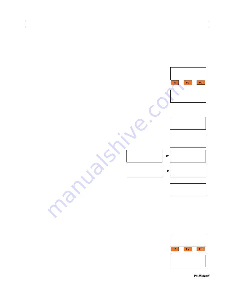
Program file
AP16101399.hex
Running:16.10.13.00
NEWPGM OLDPGM
BACK
Program file
AP16101399.hex
Running:16.10.13.00
LOAD
NEXT
BACK
Erasing
Program memory
Loading
AP16101399.hex
Record# 0
USB drive active
Offline, All STOP
LOG
UPDATE
CONFIG
Configure file
No file found
SAVE=capture config:
SAVE
BACK
13.2 Firmware Upgrade using USB
If necessary, your controller can have the firmware upgraded. Firmware is a set of instructions which tell the
controller CPU how to operate.
1- Obtain the hex file from Prominent and insert thumb drive with the new file into the USB port located behind
the Communication panel. See section 13 Capturing Data.
2- Press
F2
, UPDATE
3- The display shows the current hex file in use.
“NEWPGM” is a list of hex programs on the drive.
If NEWPGM is not a choice,
there are no compatible hex files on the USB drive.
“OLDPGM” is a list of hex programs on
the Aegis. If OLDPGM is not a choice,
there are no other backup hex files in the Aegis memory.
Choose New or Old to see a list of hex files.
4- Press
F2
to scroll through the list of hex files. Press
F1,
Load
to install the new
hex file.
5-
Remove the USB drive when prompted.
NOTE: OLDER FIRMWARE VERSIONS USE STEP 6.
6- The firmware is copied to the controller. When
complete Aegis will notify you to remove the USB
drive.
7- After you remove the drive, the controller will erase
the existing firmware and install the new one.
8- Once the new firmware is installed, the controller
will restart.
13.2.1 USB
–
Save or Load the Program
A program is a list of instructions that the user can edit. Set-points, calibrations, names of I/O are all saved in the
program.
13.2.1.1 Saving to the USB
1- To
save
a copy of your current program onto a USB drive, insert a USB into the USB port located behind
the Communication panel. See section
13 Capturing Data.
2- Press
F3
Config
3- If you have not previously saved a program on this USB you can only
F1
SAVE
a copy to the USB.
USB drive active
Offline, All STOP
LOG
UPDATE
CONFIG
Hardware startup
Now…………
..
Copying…
.
Program file
AP16101399.hex
0.02% Complete
Copying…
.
OK. Ready to program
Remove USB drive
100.00% Complete
Program file
OK. Ready to program
Remove USB drive