background image


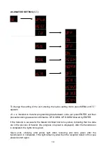
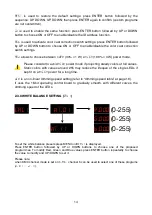
2.3.10 COLOR CORRECTION SETTING (

CAL2

CAL2        RGb       R.255


G.255 

                      b.255


To set the color correction setting press MENU until 

CAL2

 is displayed, then press ENTER button. 

Press ENTER button repeatedly to choose the value to modify and UP/DOWN to set it.

2.3.11 KEY PROTECTION SETTING (

KEY


KEY         OFF. 
            ON.  

Lock  the  keys  to  prevent  unwanted  changes.  Press  MENU  until 

KEY

  is  displayed,  then  press 

ENTER and UP/DOWN to select ON (or OFF to turn it o

).

2.4 DMX CONSOLE OPERATION 

2.4.1 CHANNEL TABLE 

A total of five DMX channel modes are available:   

STAG, ARC.1, AR1.d, AR1.S, HSV. 

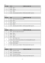
STAG

 (default)

CHANNEL

DATA

CONTROL FUNCTION

1

0-255

Dimming (master intensity level)

2

0-255

Red (when CH.7 chooses PR.01-10, CH.2 controls Time (reference: Edit Menu 
page 12)

3

0-255

Red (when CH.7 chooses PR.01-10, CH.3 controls Fade Time (reference: Edit 
Menu page 12)

4

0-255

Blue

5

0-9

No change in color

10-255

Color change mode (reference: “Color Changing Table” page 18)

6

0-9

No strobe effect

10-255

Strobe speed

15

(25-255)

(25-255)

(25-255)

Summary of Contents for ARCHILED RGB

Page 1: ...INSTRUCTION MANUAL ARCHILED RGB WARNING Read this instruction manual carefully before using the projector Thank you for choosing a PROIETTA product ...

Page 2: ...1 BASIC USAGE 2 1 2 KEYPAD LOCK 2 2 MENU STRUCTURE 2 3 MENU DESCRIPTION 2 3 1 STATIC MODE STAT 2 3 2 AUTO MODE AUTO 2 3 3 DMX AND SLAVE RUN 2 3 4 DMX ADDRESS CODE dMX 2 3 5 DMX512 CHANNEL MODE PERS 2 3 6 ID ADDRESS CODE Id 2 3 7 SCENE EDITING EdIT 2 3 8 NATIVE SETTING SET 2 3 9 WHITE BALANCE SETTING CAL1 2 3 10 COLOR CORRECTION SETTING CAL2 2 3 11 KEY PROTECTION SETTING KEY 1 2 3 3 4 5 5 6 6 6 6 6...

Page 3: ...DMX CONSOLE OPERATION 2 4 1 CHANNEL TABLE 2 4 2 COLOR CHANGING TABLE 2 4 3 DIMMING SPEED TABLE DEFAULT CUSTOM PROGRAMS WARRANTY DECLARATION OF CONFORMITY DISPOSAL OF UNUSED PRODUCT 2 15 15 18 18 19 22 23 23 ...

Page 4: ... the manufacturer who denies any responsibility for unauthorized interventions Always disconnect the projector from the outlet before any maintenance operation The risk of electric shock if you disassemble the projector or some of its parts For reliable operation of the device the ambient temperature must be between 25 C 13 F and 45 C 113 F Do not place objects on the power cable and in case of da...

Page 5: ...3 Hz LED 54 LED 18 R 18G 18B NOMINAL POWER 98 W NUMBER OF COLORS 16 000 000 LIFETIME 50 000 h CONTROLS Menu 4 buttons 4 digit display DMX 512 Master Slave IP Protection rating IP66 MINIMUM AMBIENT TEMPERATURE 25 C MAXIMUM AMBIENT TEMPERATURE 45 C WEIGHT 7 Kg DIMENSIONS See the drawings below dimensions in mm 2 ...

Page 6: ...ect up to thirty scenes per program program data can be exchanged between different units host slave 3 Static Mode It s possible to select any fixed color without the use of the console also assign the strobe effect and vary its speed STAGE MODE BLACK OUT CONTROL FROM CONSOLE AND ID ADDRESS CODE In STAG mode when predefined and custom programs run if the value of the overall brightness adjustment ch...

Page 7: ...X512 to use a DMX console while receiving a standard DMX512 signal the point after the fourth decimal point will flash If it does not flash please check if the console or any other DMX512 signal source is properly connected and transmitting if you want to change the value of the DMX address press the MENU button until you see dMX and press the ENTER button to access the sub menu this allows to set...

Page 8: ... of the connected units Please note 1 in some circumstances units may be out of sync at startup due to inconsistencies in startup times or abnormal behavior due to data packet leaks If this happens move the DMX channel cursor relative to the incorrect value setting it first to zero and then to the desired value 2 since the crystal frequency of each headlight is not exactly the same after a long ti...

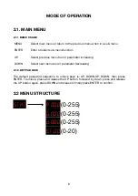
Page 9: ...asing Select next menu tool or parameter decreasing 2 1 2 KEYPAD LOCK The default password sequence to unlock keys is UP DOWN UP DOWN then press ENTER To unlock press and release the UP button followed by down press and release the UP button again press DOWN and release it finally press ENTER to confirm 2 2 MENU STRUCTURE STAT R 000 G 000 d 000 ST 00 6 0 255 0 255 0 255 0 20 MENU ENTER UP DOWN ...

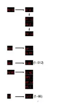
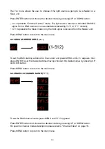
Page 10: ...AUTO AT 01 AT 10 PR 01 PR 10 RUN dMX SLAV dMX d 001 PERS STAG ARC 1 AR1 d HSV Id Id 01 7 1 512 1 66 ...

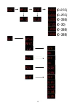
Page 11: ...EdIT PR 01 SC 01 R 000 G 000 PR 10 SC 30 b 000 ST 00 T 000 F 000 SET UPLd REST Id OFf ON RGb OFF ON POW HIGH NORM dIM OFF dIM1 dIM2 diM3 dIM4 8 0 255 0 255 0 255 0 20 0 255 0 255 ...

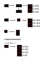
Page 12: ... WT 01 R 000 G 000 WT 11 b 000 CAL2 RGb R 255 G 255 b 255 KEY OFF ON 2 3 MENU DESCRIPTION 2 3 1 STATIC MODE STAT STAT R 000 G 000 b 000 ST 00 9 0 255 0 255 0 255 25 255 25 255 25 255 0 255 0 255 0 255 0 20 ...

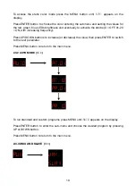
Page 13: ...g frequency Press UP DOWN buttons to increase or decrease the value then press ENTER to switch to the next parameter Press MENU button to return to the main menu 2 3 2 AUTO MODE AUTO AUTO AT 01 AT 10 PR 01 PR 10 To run standard and custom programs press MENU until AUTO appears on the display Press ENTER button to enter the sub menu and choose the desired program by pressing UP or DOWN button Press...

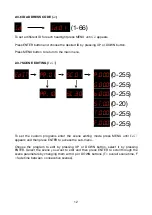
Page 14: ...on to return to the main menu 2 3 4 DMX ADDRESS CODE dMX dMX d 001 To set the DMX starting address for the current unit press MENU until dMX appears then press ENTER to set the desired address having choosen the desired value by pressing UP or DOWN button Press MENU button to return to the main menu 2 3 5 DMX512 CHANNEL MODE PERS PERS STAG ARC 1 AR1 d AR1 Sù HSV To set the DMX channel mode press M...

Page 15: ... SC 30 b 000 ST 00 T 000 F 000 To set the custom programs enter the scene editing mode press MENU until EdIT appears and then press ENTER to access the sub menu Choose the program to edit by pressing UP or DOWN button select it by pressing ENTER Select the scene you want to edit and then press ENTER to scroll through the scene parameters by changing them with Up or DOWN buttons T overall scene tim...

Page 16: ...oceed entering password confirmation UP DOWN UP DOWN followed by ENTER If the transfer is successful the Master Archiled first turns yellow indicating that the data are in the process of transfer the progress of upload is displayed After the transmission is completed the lights turns green Slave units similarly emit yellow light when receiving and turns green after the transmission in completed If...

Page 17: ...ting steady colors at full values Static colors with values around 255 may reduce the lifespan of the single LEDs if kept it on at HIGH power for a long time dIM is a non linear dimming speed setting refer to dimming speed table at page 18 It uses the 16 bit operating control board to gradually smooth with different curves the dimming speed of the LEDs 2 3 9 WHITE BALANCE SETTING CAL1 CAL1 WT 01 R...

Page 18: ...DOWN to select ON or OFF to turn it off 2 4 DMX CONSOLE OPERATION 2 4 1 CHANNEL TABLE A total of five DMX channel modes are available STAG ARC 1 AR1 d AR1 S HSV STAG default CHANNEL DATA CONTROL FUNCTION 1 0 255 Dimming master intensity level 2 0 255 Red when CH 7 chooses PR 01 10 CH 2 controls Time reference Edit Menu page 12 3 0 255 Red when CH 7 chooses PR 01 10 CH 3 controls Fade Time reference...

Page 19: ...ts a program 241 220 Custom Program PR 09 251 255 Custom Program PR 10 8 0 255 Built in program speed to adjust a custom program speed use CH2 CH3 9 0 255 Dimming speed reference Dimming Speed Table page 18 10 0 9 ID address is invalid no ID 10 19 ID1 Each decade represents an ID 200 209 ID20 210 ID21 211 ID22 Each number represents an ID 254 ID65 255 ID66 CHANNEL DATA CONTROL FUNCTION 16 ...

Page 20: ...Dimming Speed Table page 18 CHANNEL DATA CONTROL FUNCTION 1 0 255 Dimmer master intensity level 2 0 255 Red 3 0 255 Green 4 0 255 Blue 5 0 9 No change in color 10 255 Color change mode reference Color Changing Table page 18 6 0 9 No strobe effect 10 255 Strobe speed 7 0 255 Dimming speed reference Dimming Speed Table page 18 CHANNEL DATA CONTROL FUNCTION 1 0 255 H tone 0 100 2 0 255 S saturation 0...

Page 21: ... 170 200 R 100 G 100 B 100 201 255 Color temperature adjustable from CAL1 menu change every five values as follows 201 205 3 200 K 206 210 3 400 K 211 215 4 200 K 216 220 4 900K 221 225 5 600K 226 230 5900K 231 235 6 500K 236 240 7200K 241 245 8 000K 246 250 8500K 251 255 10 000K VALUE CONTROL FUNCTION 0 9 Default dimming speed set by dIM submenu of SET 10 29 Linear dimming no delay equal to OFF 3...

Page 22: ...00 000 255 00 010 008 255 000 255 00 010 008 R G B ST T F 255 000 000 00 006 003 255 255 000 00 006 003 000 255 000 00 006 003 000 255 255 00 006 003 000 000 255 00 006 003 255 000 255 00 006 003 R G B ST T F 255 000 000 00 004 001 255 255 000 00 004 001 000 255 000 00 004 001 000 255 255 00 004 001 000 000 255 00 004 001 255 000 255 00 004 001 19 ...

Page 23: ...00 255 255 10 010 010 255 255 000 10 010 010 255 000 255 10 010 010 R G B ST T F 255 000 000 08 001 001 255 064 000 07 001 001 255 064 000 00 001 001 192 000 004 08 001 001 192 032 000 10 001 001 255 000 000 08 001 001 R G B ST T F 000 255 000 00 010 001 000 000 000 00 001 001 127 000 255 00 010 001 000 000 000 00 001 001 20 ...

Page 24: ...01 001 000 064 127 00 001 001 000 255 255 00 001 001 R G B ST T F 255 000 000 08 001 001 255 064 000 07 001 001 255 032 000 00 001 001 192 000 004 08 001 001 192 032 000 10 001 001 255 000 000 08 001 001 R G B ST T F 255 000 000 00 005 005 255 000 255 00 005 005 000 000 255 00 005 005 255 000 255 00 005 005 R G B ST T F 000 000 000 00 001 000 21 ...

Page 25: ...ed description of the issue It is essential to follow the safety instructions and warnings contained in this manual Any damage caused by non compliance with the manual causes the warranty to expire The manufacturer does not take any responsibility for damages or problems caused by non compliance with the manual The only maintenance operation allowed in warranty is the replacement of the filters An...

Page 26: ...ly VAT number IT09964950019 tel 39 011 9761039 info proietta com www proietta com 23 20 DICHIARAZIONE DI CONFORMITA PROIETTA s r l Sede legale e operativa Viale dei Mareschi 4 d 10051 Avigliana To Italy Dichiara che Il dispositivo proiettore Modello Impressive 1200 2500 È progettato e realizzato in accordo con i requisiti essenziali elencati nelle seguenti direttive Direttiva 2006 95 EC del Parlam...

Reviews: