background image

8

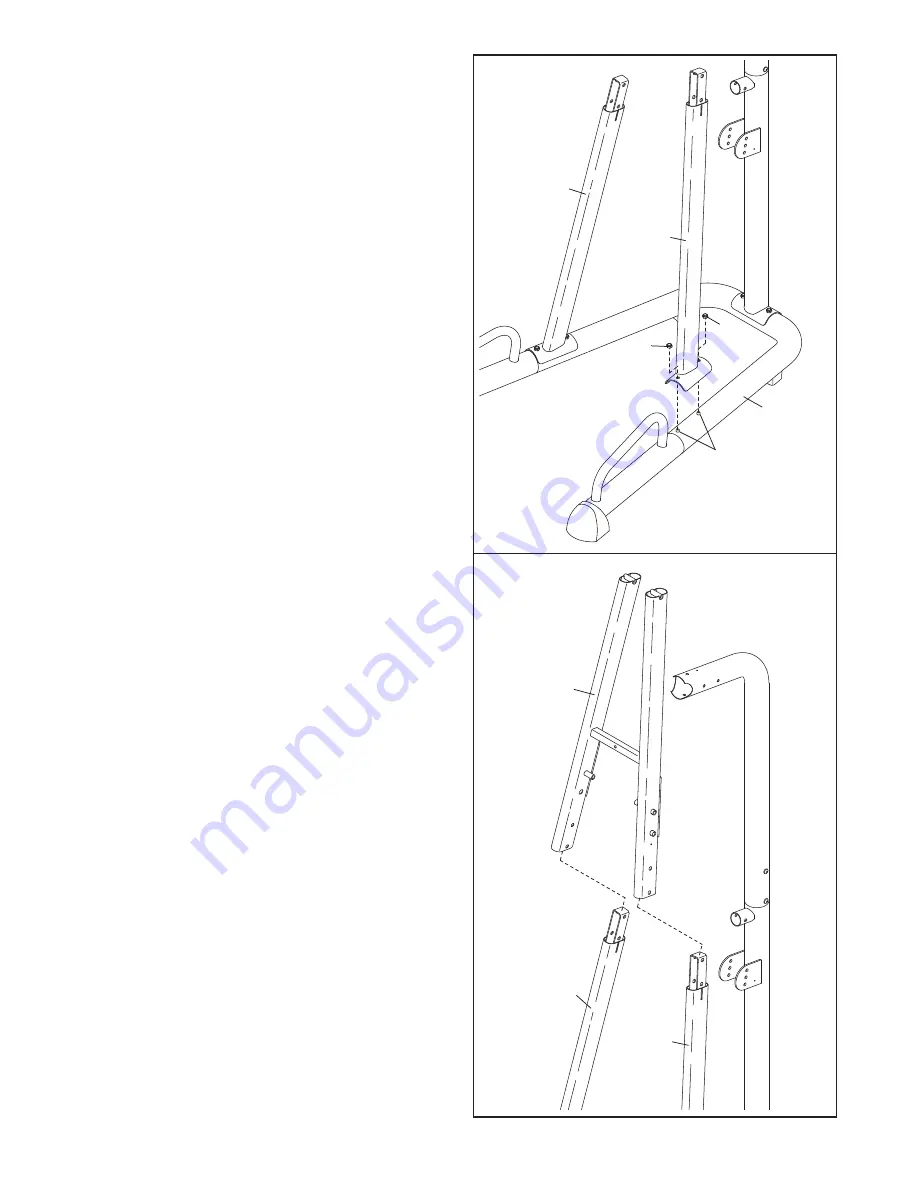
5.

Attach the Left Front Upright (50) to the Base (1)
using the indicated M10 x 90mm Button Bolts
(42) and two M10 Nylon Locknuts (35). 

Do not

tighten the Nylon Locknuts yet.

Attach the Right Front Upright (3) In the same
manner.

6.

Slide the Front Top Frame (4) onto the Left and
Right Front Uprights (50, 3).

3

5

6

50

1

42

35

35

4

3

50

Summary of Contents for fusion 2.1t

Page 1: ...PFBE1716 0 Serial No Write the serial number in the space above for future reference QUESTIONS As a manufacturer we are com mitted to providing complete customer satisfaction If you have questions or...

Page 2: ...PART IDENTIFICATION CHART 5 ASSEMBLY 6 ADJUSTMENTS 13 EXERCISE GUIDELINES 15 PART LIST 18 EXPLODED DRAWING 19 ORDERING REPLACEMENT PARTS Back Cover LIMITED WARRANTY Back Cover TABLE OF CONTENTS PROFO...

Page 3: ...Never use the knee pad without at least one resistance band connecting the support frame to the pivot arm 10 Always wear athletic shoes for foot protec tion while exercising 11 The exercise rack is d...

Page 4: ...e rack will help you to achieve the specific results you want For your benefit read this manual carefully before using the exercise rack If you have questions after reading this manual please see the...

Page 5: ...t 30 M10 x 100mm Button Bolt 31 M4 x 25mm Screw 48 M4 x 12mm Screw 49 PART IDENTIFICATION CHART Refer to the drawings below to identify small parts used in assembly The number in parentheses by each d...

Page 6: ...he packing materials until assembly is completed Tighten all parts as you assemble them unless instructed to do otherwise As you assemble the exercise rack make sure all parts are oriented as shown in...

Page 7: ...0mm Button Bolts 42 and two M10 Nylon Locknuts 35 Do not tighten the Nylon Locknuts yet 4 Attach the Rear Top Frame 6 to the Rear Upright 5 with two M10 x 90mm Button Bolts 42 and two M10 Nylon Locknu...

Page 8: ...e indicated M10 x 90mm Button Bolts 42 and two M10 Nylon Locknuts 35 Do not tighten the Nylon Locknuts yet Attach the Right Front Upright 3 In the same manner 6 Slide the Front Top Frame 4 onto the Le...

Page 9: ...Frame 6 Attach the Pull up Frame to the Rear Top Frame with four M8 x 15mm Button Screws 39 and two M8 x 62mm Button Screws 41 Tighten the M10 Nylon Locknuts 35 used in steps 2 8 7 8 4 35 35 8 30 35...

Page 10: ...o the Rear Upright 5 with an M4 x 12mm Screw 49 11 Attach the Knee Pad Cover 14 and the Knee Pad 15 to the Pad Frame 11 with two M6 x 75mm Button Screws 47 and two M6 Washers 36 11 12 47 14 15 11 47 3...

Page 11: ...29 into the Front Top Frame 4 Attach the Adjustment Pin to the Front Top Frame with an M4 x 12mm Screw 49 14 Hold the Dip Arm 10 behind the Front Top Frame 4 as shown Attach the Dip Arm with two M10 x...

Page 12: ...2mm Screw 49 Attach the Pull up Frame Cap 26 to the Pull up Frame 7 with an M4 x 25mm Screw 48 19 Make sure that all parts have been properly tightened before the exercise rack is used 17 Attach the B...

Page 13: ...up position Remove the indicated Adjustment Pin 29 and lift the Dip Handle 13 Engage the Adjustment Pin into the Front Top Frame 4 and the hole in the Dip Arm plate not shown To use the Dip Arm 10 rem...

Page 14: ...move the Knee Pad 15 out of the way lift on the Knee Pad and slide the Pad Frame 11 forward dis engaging the rod on the Assist Arm 9 Lower the Knee Pad Storage Tube 11 9 Rod L slot Notch 9 8 USING TH...

Page 15: ...and aerobic exer cise will reshape and strengthen your body plus devel op your heart and lungs PERSONALIZING YOUR EXERCISE PROGRAM Determining the exact length of time for each workout as well as the...

Page 16: ...out List the date the exercises performed the resistance used and the numbers of sets and repetitions completed Record your weight and key body measurements at the end of every month Remember the key...

Page 17: ...GHT SETS REPS EXERCISE WEIGHT SETS REPS EXERCISE WEIGHT SETS REPS AEROBIC EXERCISE AEROBIC EXERCISE TUESDAY Date WEDNESDAY Date THURSDAY Date FRIDAY Date Make photocopies of this page for scheduling a...

Page 18: ...Armrest 20 1 Top Frame Cap 21 1 Bottom Frame Cap 22 2 Base Leg Cap 23 2 Base Pad 24 6 29mm Round Inner Cap 25 1 51mm Round Inner Cap 26 1 Pull up Frame Cap 27 2 Dip Frame Cap 28 2 Pull up Handle Cap...

Page 19: ...4 15 16 17 18 18 19 19 20 21 22 22 23 23 24 24 24 24 24 24 25 26 27 27 28 28 29 29 32 33 34 35 42 35 39 43 43 43 35 35 35 35 36 36 36 36 36 37 38 38 35 35 35 35 35 40 40 41 41 43 43 43 43 42 42 39 39...

Page 20: ...se or performance of the product or damages with respect to any economic loss loss of property loss of revenues or profits loss of enjoyment or use costs of removal or installation or other consequent...

Reviews: