background image

15

You can now enter your name and your weight.
Highlight the desired option in the menu and press
the Enter button. A cursor will appear in a field in
the display. To enter a number or letter above the
cursor, press the up and down Navigation buttons.
To move the cursor, press the left and right
Navigation buttons. When you have finished enter-
ing the desired numbers or letters in the field,
press the Enter button. Repeat this action to enter
all the desired user information. Note: For more in-
formation about the RESET JOURNAL option, see
page 23.

To return to the setup menu, press the Back but-
ton. To exit the user mode, highlight the SAVE
AND EXIT option and press the Enter button. 

4. Select a default user setting.

The console can record, store, and load informa-
tion for two different users. The default user setting
allows you to choose the user information that will
be loaded and recorded when you turn on the con-
sole at the beginning of a workout session. 

To select a default user setting, first highlight the
SELECT DEFAULT USER option in the setup
menu and press the Enter button. A list of default
user options will then appear in the display.

To select a default user option, press the up and
down Navigation buttons until an arrow appears
next to the desired option. Then, press the Enter
button. When you select an option, an “x” will ap-
pear in the box next to the selected option. 

Note: You can also turn on or turn off the wel-
come screen from this menu. If the SHOW WEL-
COME SCREEN option is selected, then a wel-
come message with the name of the selected user
will appear in the display each time you turn on the
console. To turn on or turn off the welcome screen,
move the arrow to the SHOW WELCOME
SCREEN option and press the Enter button.

To exit the default user menu, press the Back but-
ton. The setup menu will then appear in the dis-
play.

5. Set the date and time.

Setting the date and time will allow the console to
record your workout history accurately in the fit-
ness journal.

To set the date and time, first highlight the
CHANGE DATE OR TIME option in the setup
menu and press the Enter button. The date setting
will then appear in the display. 

To set the date, first press the left and right
Navigation buttons to highlight the month, day, or
year field. Then, press the up and down Navigation
buttons to select the desired month, day, or year. 

When you have finished setting the date, press the
Enter button. The time setting will then appear in
the display.

To set the time, first press the left and right
Navigation buttons to select the hour or minute
field. Then, press the up and down Navigation but-
tons to select the desired hour or minute; 

make

sure to select the correct AM or PM time in the
hour field. 

When you have finished setting the

time, press the Enter button. The console will then
exit the user mode.

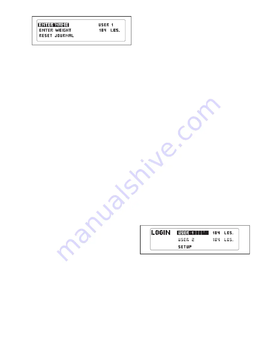
HOW TO IDENTIFY YOURSELF AS USER 1 OR
USER 2

The console can load information and keep track of the
workout history for two different users. To identify your-
self as User 1 or User 2 for a workout session, first
press the Enter button and enter the user mode. 

The word LOGIN will appear in the display for a few
seconds and then the login menu will appear. Press
the up and down Navigation buttons to highlight USER
1 or USER 2. Note: If you have personalized the con-
sole settings (see page 14), then the name you en-
tered will appear instead of USER 1 or USER 2.

Press the Enter button to confirm your choice. The
console will then exit the user mode.

Summary of Contents for 810 Tr Treadmill

Page 1: ...ns or if parts are missing PLEASE DO NOT CONTACT THE STORE please contact Customer Care IMPORTANT You must note the product model number and serial number see the drawing above before contacting us CA...

Page 2: ...er LIMITED WARRANTY Back Cover 2 The decals shown here have been applied in the locations shown If a decal is miss ing or illegible call the telephone num ber on the front cover of this manual and req...

Page 3: ...se an extension cord 12 Use only a single outlet surge suppressor that meets all of the specifications described on page 12 To purchase a surge suppressor see your local PROFORM dealer or call the tel...

Page 4: ...ill make sure that the frame is held securely in the storage position 23 Never insert any object into any opening on the treadmill 24 Inspect and properly tighten all parts of the treadmill regularly...

Page 5: ...tions after read ing this manual please see the front cover of this man ual To help us assist you note the product model number and serial number before contacting us The model number and the location...

Page 6: ...soft cloth and a mild non abrasive cleaner Assembly requires the included hex keys and your own Phillips screwdriver adjustable wrench and needlenose pliers Use the drawings below to identify the asse...

Page 7: ...Upright near the Base 83 Then pull the other end of the long tie until the Upright Wire is routed completely through the Right Upright 83 38 78 79 38 3 Long Tie Long Tie 78 38 1 Make sure that the pow...

Page 8: ...3 8 Star Washer 9 into the Left Upright and the Bolt Spacer Repeat this step with a sec ond Bolt Spacer 88 3 8 x 4 1 2 Bolt 6 and 3 8 Star Washer 9 Then set the Left Upright in the Left Upright Space...

Page 9: ...Set the console assembly on the Right Upright 78 and Left Upright not shown Be careful not to pinch the wires Console Assembly Console Wire Long Tie 38 78 9 38 Console Wire 7 Set the console assembly...

Page 10: ...move the Frame back and forth to align the Storage Latch with the bracket Lower the Frame 56 see HOW TO LOWER THE TREADMILL FOR USE on page 25 53 8 8 Large Barrel 83 4 56 14 12 4 11 Identify the Stor...

Page 11: ...s Door 87 with the two in cluded small screws 3 Make sure that no wires are pinched Reattach the Access Door 87 with the 8 x 3 4 Screws 1 Discard the other wires in cluded with the receiver A 87 Small...

Page 12: ...nc tion or break down grounding provides a path of least resistance for electric current reducing the risk of elec tric shock This product is equipped with a cord having an equipment grounding conduct...

Page 13: ...ave them for future use The console also features a fitness journal which auto matically records and stores your exercise information so that you can view your workout history and track your progress...

Page 14: ...g belt and center the walking belt if neces sary see page 28 Note The console can display speed and distance in either miles or kilometers To find out which unit of measurement is selected or to chang...

Page 15: ...rn on or turn off the welcome screen move the arrow to the SHOW WELCOME SCREEN option and press the Enter button To exit the default user menu press the Back but ton The setup menu will then appear in...

Page 16: ...Start button the Speed increase button or one of the twelve num bered speed buttons 5 Change the incline of the treadmill as desired To change the incline of the treadmill press the Incline increase...

Page 17: ...s on the handrail avoid moving your hands When your pulse is de tected your heart rate will be shown For the most accurate heart rate reading continue to hold the contacts for about 15 seconds 8 When...

Page 18: ...programmed for the second segment the speed and or incline setting will flash in the display for a moment to alert you The treadmill will then automatically adjust to the speed and incline settings fo...

Page 19: ...f tones will sound The speed of the walking belt will then increase to 6 5 mph To change the speed of the walking belt or the in cline of the treadmill at any time during the work out press the Speed...

Page 20: ...you press the Start button the walking belt will begin to move Hold the handrails and begin walking Each custom workout is divided into one minute segments One speed setting and one incline set ting...

Page 21: ...e same way as a classic workout see step 4 on page 18 If desired you can redesign the workout while using it To change the speed setting or the in cline setting for the current segment simply press th...

Page 22: ...Navigation buttons to change the year Note The fitness journal can store information for 11 different years 5 View exercise information by month After a few seconds the view month menu will ap pear in...

Page 23: ...and allows you to select a unit of measurement for the console turn on or turn off the display demo mode and set the contrast of the display To select the information mode hold down the Stop button in...

Page 24: ...To use the Integrated Universal Dock for iPod locate the iFIT Universal iPod Connector Plug one end into the Integrated Universal Dock for iPod near the speak ers and the other end into your iPod Make...

Page 25: ...30 C HOW TO MOVE THE TREADMILL Before moving the treadmill convert the treadmill to the stor age position as described above Make sure that the latch knob is locked in the storage position 1 Hold a h...

Page 26: ...he circuit breaker has tripped wait for five minutes and then press the switch back in b Make sure that the power cord is plugged in If the power cord is plugged in unplug it wait for five minutes and...

Page 27: ...ey After a few seconds re insert the key The treadmill will automatically rise to the maximum incline level and then return to the minimum level This will recalibrate the incline system PROBLEM The wa...

Page 28: ...n the power cord insert the key and run the treadmill for a few minutes Repeat until the walk ing belt is centered b If the walking belt slips when walked on first re move the key and UNPLUG THE POWER...

Page 29: ...goal is to strengthen your cardiovascular system you must perform aerobic exer cise which is activity that requires large amounts of oxygen for prolonged periods of time For aerobic ex ercise adjust t...

Page 30: ...t Wire 39 1 Lift Frame Ground Wire 40 1 Left Rear Foot Insert 41 1 Left Foot Rail 42 1 Warning Decal 43 2 Platform Cushion 44 1 Walking Platform 45 1 Walking Belt 46 2 Belt Guide 47 1 Console Tray 48...

Page 31: ...Wire 102 1 iFIT Universal iPod Connector 103 1 5 32 Hex Key 104 1 Lift Motor Spacer 105 2 Front Frame Endcap 106 1 Right Accessory Tray 107 2 Hood Screw 108 1 Latch Endcap User s Manual These parts ar...

Page 32: ...1 30 31 30 60 59 24 24 29 29 46 46 105 25 25 25 25 97 41 36 36 36 49 50 105 48 36 44 42 45 49 51 58 56 57 57 48 27 40 3 103 4 90 54 53 8 8 25 25 25 25 55 97 16 16 32 32 43 43 107 32 EXPLODED DRAWING A...

Page 33: ...11 11 11 11 72 15 71 12 24 24 68 69 28 24 67 66 73 70 39 19 19 26 64 63 62 65 107 107 37 37 37 1 1 1 61 EXPLODED DRAWING B Model No PFTL79807 0 R1007A 33...

Page 34: ...1 2 81 2 81 2 84 8 8 84 4 21 22 77 77 75 23 23 8 8 74 83 82 76 79 82 13 81 2 13 104 86 85 52 4 8 14 38 6 9 78 6 9 93 7 10 10 7 7 10 7 10 38 6 88 88 9 4 34 EXPLODED DRAWING C Model No PFTL79807 0 R1007...

Page 35: ...1 92 24 101 91 89 99 1 1 1 1 1 1 1 1 1 1 1 1 1 5 33 106 98 96 94 100 1 87 35 102 1 1 5 33 98 95 98 98 80 80 1 1 47 35 EXPLODED DRAWING D Model No PFTL79807 0 R1007A...

Page 36: ...e customer will be responsible for a minimal trip charge This warranty does not extend to any product or damage to a product caused by or attributable to freight damage abuse misuse im proper or abnor...

Reviews: