


PS-4600 Series User Manual
129
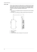
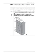
COM Expansion Board Description
Overview
The figure shows the COM Expansion Board:
1
LED
2
Switch
A terminating resistor for the serial interface is already integrated on the interface
module. There is a switch to connect or disconnect the terminating resistor, but the
Industrial Personal Computer unit needs to be opened in order to reach it. An active
terminating resistor is indicated by a yellow LED.
Serial Interface
The serial interface of the COM Expansion Board is a combined RS-232C/RS-
422/RS-485 interface with D-SUB 9 pin connector.
The operating mode (RS-232C/RS-422/RS-485) is selected automatically,
depending on the electrical connection. The serial interface and COM Expansion
Board use a different pin assignment for RS-232C communication.
When using the COM Expansion Board for RS-232C communication, pins 1, 4, 6
and 9 are not connected to anything.
The table provides the technical data of the serial interface:
Element
Characteristics
Amount
1
Type
RS232/422/485, modem-capable, electrically isolated
UART
16550-compatible, 16-byte FIFO
Transfer Rate RS232
Maximum 115 kbps with cable length
10 m
Maximum 64 kbps with cable length
15 m
Transfer Rate RS422/485
Maximum 115 kbps with cable length
1200 m
Power Consumption
1 W
Connection
D-sub 9 pin, plug
Ambient Temperature:
Operation
Storage
Transport
0...55
C (32...131
F)
–20...60
C (–4...140
F)
–20...60
C (–45...140
F)
Relative Humidity:
Operation
Storage
Transport
5...90 %, non-condensing
5...90 %, non-condensing
5...90 %, non-condensing
Weight
35 g (1.23 oz)
Summary of Contents for PS-4600 Series
Page 1: ......
Page 12: ...About the Book 12...
Page 14: ...General Overview 14...
Page 26: ...Important Information 26...
Page 56: ...Implementation 56...
Page 72: ...Industrial Personal Computer Connections 72...
Page 78: ...Configuration of the BIOS 78 Platform Information The figure shows the Main submenu...
Page 118: ...Hardware Modifications 118 The figure shows the dimensions of the UPS battery unit...
Page 170: ...Hardware Modifications 170...
Page 172: ...Installation 172...
Page 192: ...192...
Page 196: ...After sales service 196...


