background image

3 - 6

PL-6700 Series User’s Manual

Optional Units and Expansion Boards

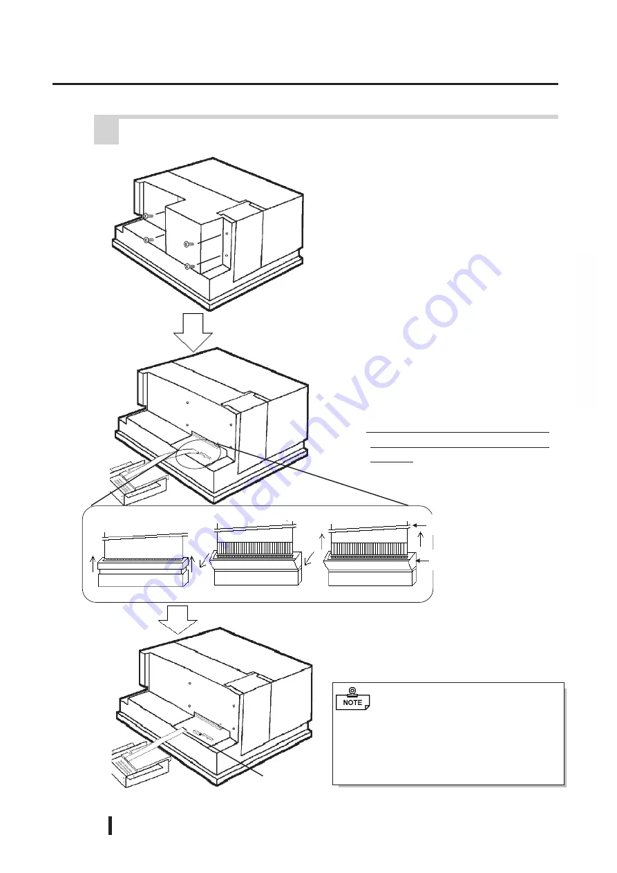
1)  Remove the floppy disk unit cover’s

four attachment screws.

3)  Remove the cable end from the

FDD connector.

 3    Removing or Installing the FDD Unit (PL-FD100)

Cable End

Raise Pinch Collar

2) Around the FDD connection cable

is fitted a black plastic pinch col-
lar (Part of the PL’s connector - see
detail 1, page 3-7).

     This pinch collar must be pulled up

to release the connection cable’s
end tab.

Slide collar sideways

Remove FDD cable

FDD Connector Cable

Pinch Collar

When either exchanging or installing
the PL-FD100, before screwing in the
unit’s attachment screw, be sure that the
FDD Connection Cable is attached and
the abovementioned connector’s pinch
collar is in place.

Summary of Contents for PL-6700 Series

Page 1: ...PL 6700 Series Panel Computer User s Manual Digital Electronics Corporation...

Page 2: ...to change without notice 3 This manual was written with care however if you should find any error or omis sions please contact Digital Electronics and inform them of your findings 4 Please be aware t...

Page 3: ...future reference SafetyIcons This manual uses the two icons below to call attention to information important for the safe and correct use of the PL Please pay attention to these icons and follow all...

Page 4: ...icles water or other types of liquids contact any of the PL s inter nal parts immediately turn the unit s power OFF unplug the power cord and contact either your dealer or Digital Electronics Corporat...

Page 5: ...toring the PL near chemicals or where chemicals can come into contact with the unit Since the PL 6700 s hard disk drive HDD is a consumable item i e it has a definite usage lifetime be sure to back up...

Page 6: ...on about the PL s LCD panel please contact your local PL distributor The Digital Electronics Corporation cannot be held responsible or pro vide any compensation for damage s caused by the loss of data...

Page 7: ...nt PL6700 T4 UL Registration Model No 0880044 1 PL6700 S4 UL Registration Model No 0880044 2 If the PL is installed so as to cool itself naturally be sure to install the PL in a vertical position Also...

Page 8: ...ly mounted into a metal panel IP 6 5 f 1 2 3 4 1 Designates the type of protection provided 2 Indicates the degree of protection provided to the human body by the unit and the degree of protection pro...

Page 9: ...ations 2 1 2 1 1 Electrical Specifications 2 1 2 1 2 Environment Specifications 2 1 2 1 3 Dimensions 2 1 2 2 Performance Specifications 2 2 2 2 1 Performance Specifications 2 2 2 2 2 Display Functions...

Page 10: ...ation and Wiring 4 1 Installation Cautions 4 1 4 2 Installing the PL 4 3 4 2 1 Installation Procedures 4 3 4 3 Wiring the PL 4 6 4 3 1 Connecting the Power Cord 4 6 4 3 2 Power Supply Cautions 4 8 4 3...

Page 11: ...eaning the Display 7 1 7 2 Filter Cleaning 7 2 7 3 Periodic Maintenance Check Points 7 3 Appendices 1 Hardware Configuration A 1 1 1 I O Mapping A 1 1 2 Memory Mapping A 3 1 3 IRQ Mapping A 4 2 Serial...

Page 12: ...titions For details concerning these procedures refer to the OS maker s installation manual For system setup and OS installation a PS 2 type keyboard is necessary When using Windows NT4 0 Windows 95 b...

Page 13: ...or cost performance Digital s STN type LCDs provide a high quality color display that rivals our TFT at a reasonable price Easy Front Panel Installation The PL is designed to be installed easily into...

Page 14: ...ful when installing the PL 6700 to not damage the built in HDD Installation Brackets 8 PL6700 Floppy Disks 2 Power Cord PL 6700 Unit PL 6700T PL 6700S This cord is designed only for 100V use Any other...

Page 15: ...instruc tions given with this icon to insure the safe operation of the PL Contains additional or useful information Indicates terms or items that require further explanation See the footnote on that...

Page 16: ...TN TFT Analog Resistance Film Touch Panel AC IN 85 to 132V 170 to 265V ISA Slots 4 2 PCI slots are also available DIMM sockets 2 Power Supply Unit DC 5V 12V Commercial items Optional Unit s Mouse Keyb...

Page 17: ...rovides 5V and 12V power to expansion slots Can provide a total of 200mA of current sum of all four slots CD ROM Drive Unit PL DK200 IDE ATAPI compliant CD ROM drive unit Connection cable is included...

Page 18: ...6 7 00 x42 HU01x PL 6700 series 1 3 PL Series Panel Types HDD Revision No Display Panel Type STN Color LCD PL 6700S TFT Color LCD PL 6700T Display type S STN color LCD T TFT color LCD PL 6700 s revisi...

Page 19: ...1 4 PL 6700 Series User s Manual Overview MEMO This page intentionally left blank...

Page 20: ...P65f JEM1030 2 1 General Specifications 2 4 PL External Features 2 5 PL Dimensions Chapter 2Specifications 1 The front face of the GP unit installed in a solid panel has been tested using conditions e...

Page 21: ...onnector Keyboard PS 2 Interface mini DIN 6 pin female connector side front Mouse PS 2 Interface mini DIN 6 pin female connector side RGB Output Analog RGB Output FD Unit Front Access 2 modes Front an...

Page 22: ...this service please contact your nearest authorized distributor Slots 2 and 3 can be used for either PCI or ISA cards The distance pitch between the 1st and 4th slots and their adjacent slots is 20mm...

Page 23: ...UT 1 T S 16 INIT OUT O D 4 DATA2 OUT 1 T S 17 SLCTIN OUT O D 5 DATA3 OUT 1 T S 18 GND 6 DATA4 OUT 1 T S 19 GND 7 DATA5 OUT 1 T S 20 GND 8 DATA6 OUT 1 T S 21 GND 9 DATA7 OUT 1 T S 22 GND 10 ACKNLG IN T...

Page 24: ...Name Pin No Signal Name 1 CD 6 DSR 2 RXD 7 RTS 3 TXD 8 CTS 4 DTR 9 RI 5 GND 5 CRT Interface Video Pin No Signal Name Pin No Signal Name 1 R 9 NC 2 G 10 GND 3 B 11 NC 4 NC 12 RESERVE NC 5 GND 13 H SYN...

Page 25: ...actory set at the optimal level adjustment is usually not necessary Front Face of PL Pushing both slide locks outwards will open the Maintenance Cover Turning the contrast knob to the right clockwise...

Page 26: ...Connector COM1 RS 232C Connector COM2 RS 232C Connector COM3 RS 232Cinterfaces DB9 pinmaleconnectors which allow communication with other computers or connec tion to peripheral devices HDD Cover When...

Page 27: ...p Connect the 100V 240V AC power cord here Power Switch Use this switch to turn the PL s power ON or OFF Half Cover When attaching the optional DIM module or other optional expansion boards you will n...

Page 28: ...2 5 PL Dimensions 1 PL 6700T PL 6700S General Dimensions Unit mm excluding projections Side View Side View Opposite Side 174 13 2 270 9 For detailed PL dimension information please contact your local...

Page 29: ...2 10 PL 6700 Series User s Manual Chapter 2 Specifications Rear Face Top Face 330...

Page 30: ...fore starting this work The PL s full sized board and cover cannot be attached first and then the unit installed due to size differences When using a full sized expansion board be sure to check its di...

Page 31: ...Installation Slot Dimensions Unit mm Be sure the thickness of the panel is from 1 6 to 10 mm To insure that the PL s water resistance is maintained be sure to install the PL into a panel that is flat...

Page 32: ...odule for expansion Installed inside the PL DIM Module PL EM230 64MB SDRAM Main memory module for expansion Installed inside the PL HDD Unit PL HD200 Built in type special purpose 2 5 inch HDD unit Us...

Page 33: ...ompatible with Digital s PL unit Installing incompatible boards may result in either damage to or failure of the PL and will void your warranty PCI Bus Within the entire range of PCI buses currently a...

Page 34: ...binet since this could damage either the leg the PL or the panel In order to perform development using the PL 6700 an additional leg support is supplied with the unit to stabilize it when placing it o...

Page 35: ...how to install a second DIM module in that socket 2 Remove the half cover it will pivot out and away from the unit and then the rear maintenance cover 1 Unscrew the five 5 attachment screws used to h...

Page 36: ...le s clips lock in place 6 Then tilt the module down so that the module and socket s contacts are parallel Push here Alignment Slots Be sure to only push on the points shown here Pushing on any other...

Page 37: ...FDD connection cable is fitted a black plastic pinch col lar Part of the PL s connector see detail 1 page 3 7 This pinch collar must be pulled up to release the connection cable s end tab Slide colla...

Page 38: ...the HDD unit s protective cover s 2 attachment screws 2 Remove the HDD unit s cover and unscrew the HDD unit s 2 set screws Follow the steps given below when attaching or detaching the PL HD100 3 Pul...

Page 39: ...refully Connect to the PL HD100 HDD Connector Cable Be sure not to bend any of the HDD s connector pins while removing the cable s connector Do not use these pins Figure 1 PL HD100 Connector Figure 1...

Page 40: ...section Swings out away from the unit 2 Remove the half cover it will pivot out and away from the unit and then the rear maintenance cover 1 Unscrew the five 5 attachment screws used to hold the rear...

Page 41: ...place with the attachment screws Insert board here Expansion Board Insert board here Expansion Board 4 Remove the desired expansion slot s blank panel by unscrewing the panel s attachment screw Panel...

Page 42: ...ese pins Figure 1 PL HD100 Connector Figure 1 PL HD100 Connector Figure 1 PL HD100 Connector Figure 1 PL HD100 Connector Figure 1 PL HD100 Connector Cable Inversion Prevention Pin Removed Connect the...

Page 43: ...onnect the cable s middle connector to the main board s HDD connector Be sure to connect the CD ROM drive connector cable s 1 pin mark side with the IDE interface s 1 pin DC Power Cable Connect to DC...

Page 44: ...ted Cautions Be sure to confirm that the area near the PL will be within the allowable temperature range If this area s temperature exceeds the allowed limit a machine breakdown can occur Also be sure...

Page 45: ...he PL to malfunction PL Condition Shock Strength When using the HDD Up to 0 5G When using the FDD Up to 1 0G When using no drives Up to 2 0G Be sure to not move the PL unit while the HDD is starting u...

Page 46: ...to the seal s groove which runs around the perimeter of the panel s frame Create a mounting hole Create a hole for mounting the PL like that pictured here These two items the moisture resistant packin...

Page 47: ...itches and non fuse breakers Avoid using the PL in environments where corrosive gases are present Insert the PL into the installation slot Secure the rear panel of PL in place with the mounting Side p...

Page 48: ...attachment hole and slide the bracket backwards until it stops 4 Use a screwdriver to tighten the bracket s adjustment screw To ensure a high degree of moisture resistance the torque should be 0 5 to...

Page 49: ...these two termi nals provides 100V to 240V AC power L live and N Neutral This terminal is connected to the PL s frame chassis screw size M3 4 3 Wiring the PL 1 Connecting the Power Cord To prevent el...

Page 50: ...nd tighten the screws Crimp Terminal Types V1 25 3 by J S T or equivalent JIS standard part number RAV1 25 3 Crimp terminals must be the same as shown below 3 Reattach the terminal strip s transpar en...

Page 51: ...attach a ferrite core to the power cord Isolate the main circuit high voltage large current line I O signal lines and power cord and do not bind or group them together To prevent damage from lightning...

Page 52: ...ure b c Shared ground not allowed 3 Grounding Cautions PL PL Other device Other device 4 Cautions When Connecting I O Signal Lines I O signal lines must be wired separately from the power circuit cabl...

Page 53: ...4 10 PL 6700 Series User s Manual Optional Units and Expansion Boards MEMO This page intentionally left blank...

Page 54: ...e factory Normally use only the factory default settings STANDARD CMOS SETUP BIOS FEATURES SETUP CHIPSET FEATURES SETUP POWER MANAGEMENT SETUP PNP PCI CONFIGURATION LOAD BIOS DEFAULTS LOAD SETUP DEFAU...

Page 55: ...he PL s internal floppy disk drive The selection 1 44MB 3 5in is recommended The other available settings are 720K 3 5in 1 2M 5 25in 360 5 25in 2 88M 3 5in or None The 1 44M 3 5in selection is factory...

Page 56: ...most users When the BIOS setup utility s Text Expansion feature is set to Expansion and the English DOS 50 Character Display Mode is used the screen s display will expand horizontally not vertically V...

Page 57: ...led selection is factory set and recommended for most users Boot Sequence Designates the drive order used by the OS during start up The possible selections are C only A C C A C CDROM A or CDROM C A Th...

Page 58: ...the Password Entry Setup used during BIOS setup or System which is used during BIOS setup and Startup When the Supervisor Password or User Password area s password has not been designated this setting...

Page 59: ...Paging 1T Refresh Cycle Time us 15 6 RAS Pulse Width Refresh 6T RAS Precharge Time 5T RAS to CAS Delay 5T CAS Pulse Width FP 2T CAS Pulse Width EDO 1T RAMW AssertionTiming 3T CAS Precharge Time FP 2T...

Page 60: ...ection is factory set and recommended for most users Suspend Option When Auto Configuration Enable has been selected this selection cannot be used The Static Suspend selection is factory set and recom...

Page 61: ...or most users Suspend Mode Only after Auto Configuration has been set to User Define can the Suspend Mode be used The Disabled selection is factory set and recommended for most users COM Ports Activit...

Page 62: ...NITIAL SETTING IRQ 3 assigned to Legacy ISA IRQ 10 assigned to Legacy ISA IRQ 4 assigned to Legacy ISA IRQ 11 assigned to Legacy ISA IRQ 5 assigned to PCI ISA PnP IRQ 12 assigned to PCI ISA PnP IRQ 7...

Page 63: ...utomatically by the PCI or fixed as ISA The two selections available are PCI AUTO or ISA The PCI AUTO selection is factory set and recommended for most users Primary IDE INT Only after selecting the P...

Page 64: ...Primary can these IDE Primary Slave PIO settings be entered The two selections available are Disabled or Enabled The Disabled selection is factory set and recommended for most users IDE Date Port Post...

Page 65: ...Q7 or 278 IRQ5 When any selection other than Disabled is used EPP ECP Compatible or Extended must also be selected Also if EPP has been selected either Ver 1 7 or Ver 1 9 must be selected Last if ECP...

Page 66: ...D AUTO DETECTION SETUP HARD DISKS TYPE SIZE CYLS HEAD PRECOMP LANDZ SECT0R MODE Primary Master Note Some OS like SCO UNIX must use NORMAL for Installation ROM PCI ISA BIOS 2A5IIU1C CMOS SETUP UTILITY...

Page 67: ...formatting of the hard disk Normally unused 8 HDD LOW LEVEL FORMAT SETUP ROM PCI ISA BIOS 2A5IIU1C CMOS SETUP UTILITY AWARD SOFTWARE INC Primary Master 1632 3162 16 65535 3161 63 Auto Primary Slave 0...

Page 68: ...ppy Disk File List The Digital Electronics Corporation has prepared the following additional program files which are not supported by the standard version of Windows 95 or Windows NT This chapter desc...

Page 69: ...6 2 PL 6700 Series User s Manual Bundled Software MEMO This page intentionally left blank...

Page 70: ...Do not clean the unit with thinner organic solvents or strong acids Do not use sharp or hard objects such as a mechanical pencil or screwdriver to push on the display This could damage the unit Use t...

Page 71: ...stance Be sure to change the gasket periodically or when scratches or dirt become visible Important Reference About the Moisture Resistant Gasket 1 Remove the cooling fan cover s two 2 attachment scre...

Page 72: ...ditions Is the connection cable firmly connected not loose Are any bolts or screws loose Are there any flaws or tears in the moisture resistant packing Display Conditions Is the display bright enough...

Page 73: ...Maintenance and Inspection 7 4 PL 6700 Series User s Manual MEMO...

Page 74: ...board H8 3332 0070H 007FH Real time clock NMI mask 0080H 009FH DMA bank register 00A0H 00BFH Interrupt controller 8259A 00C0H 00DFH DMA controller 2 8237 00F0H 00FFH Numeric data processor 016CH 016FH...

Page 75: ...ress 16EH is used by the PL system do not assign it to other devices Sw1 to Sw4 Circuit board switch SW s lead CPU Fan H normal L Fan alarm Power Fan H Fan alarm L normal Bit7 Bit6 Bit5 Bit4 Bit3 Bit2...

Page 76: ...BIOS ROM 80 KB DRAM area 64 MB BIOS ROM 80 KB Extended ROM area 1 VGA BIOS V RAM Main memory 640 KB 4000000H 100000H 0EC000H 0A0000H 000000H 0C0000H 0CC000H 2 Memory Mapping 1 This area is reserved fo...

Page 77: ...de from controller 2 IRQ 3 Serial port 2 COM2 General Use port IRQ 4 Serial port 1 COM1 General Use port IRQ 5 Available to User IRQ 6 Floppy disk controller IRQ 7 Parallel port 1 LPT1 Printer port IR...

Page 78: ...ommunication This section explains how to perform serial communications with the PL RS 232C COM1 COM2 COM3 Cable Connections 1 CD 1 FG 1 CD 1 FG 2 RD 2 SD 2 RD 2 SD 3 TD 3 RD 3 TD 3 RD 4 DTR 4 RTS 4 D...

Page 79: ...able Connections Printer 36 pin connector PL Dsub 25 pin male connector 11 1 STROBE 19 14 AUTOFD 12 2 DATA 0 20 15 ERROR 13 3 DATA 1 21 16 INIT 14 4 DATA 2 22 17 SLCTIN 15 5 DATA 3 23 18 GND 16 6 DATA...

Page 80: ...te 0 319 639 Y coordinate 0 199 Y coordinate in new graphic mode 0 XXX Light pen line position in character units Light pen column position in character units Switching active page AH AL 05h Page No S...

Page 81: ...CX DX 0Ch Attribute Page No X coordinate Y coordinate Reading point in graphic mode AH BH CX DX 0Dh Page No X coordinate Y coordinate AL Attribute Writing character attribute at cursor position and mo...

Page 82: ...g pallet page AH AL BL BH 10h 13h 01h Expansion pallet page No Reading expansion pallet register AH AL BX 10h 15h Expansion pallet register to read Reading block in expansion pallet register AH AL ES...

Page 83: ...user defined table 8 x 14 dot font registration PC character set inside video BIOS ROM Video controller auto set AH AL BL 11h 11h Character generator bank No 8 x 8 dot font registration PC character...

Page 84: ...eturn 8 x 8 font 80h address with 4 ES BP register 5 Reserved CX DL ES BP Number of vertical bits per character Number of lines per screen 1 Address of data specified in BH Performance selection Readi...

Page 85: ...cter in character string Top address in character string Character output and attribute selection without cursor movement AH AL BH CX DH DL ES BP 13h 02h Page No Number of characters Starting line pos...

Page 86: ...of data save area AL 1Ch Successfully executed Status save as AH AL CX ES BX 1Ch 02h Request status Bit 0 Video hardware status Bit 1 Video BIOS data area Bit 2 Expansion pallet register ssave restor...

Page 87: ...Timer overflowed Hard disk status table Status Description 00h 01h 02h 04h 07h 08h 10h 20h 40h 80h BBh Successfully completed Wrong command sent Cannot find address mark Cannot find requested sector D...

Page 88: ...o Insignificant 8 bits Track Cylinder No Significant 2 bits Bits 7 8 Head No Drive No Top address in format data table CY AH 0 Successfully completed 1 Error Status Reading drive parameters AH DL 08h...

Page 89: ...oppy disk unchanged 02h Disk was changed 03h Hard disk Media change check AH DL 16h Drive No AH 00h Disk unchanged 01h Inconsistent parameter 06h Disk was changed Carry bit ON 80h Drive not ready Sett...

Page 90: ...rt No AH Line control status Bit 7 Time over error Bit 6 Transmission shift register empty Bit 5 Transmission hold register empty Bit 4 Break detected Bit 3 Framing error Bit 2 Parity error Bit 1 Over...

Page 91: ...ec units CY 0 Successfully completed 1 Already triggered or not supported Transmitting memory block in protect mode AH ES SI 87h Top address in descriptor ZF CY AH 1 Successfully completed 1 Error 00h...

Page 92: ...code AL 00h Successfully completed 01h No available space in buffer CY 1 Wiring data by key input 101 AXkeyboard compatible AH 10h AH AL Secondary code Primary code Character code Data check by key i...

Page 93: ...CD Summertime option 0 or 1 End status 0 Successfully completed 1 Error Setting time AH CH CL DH DL 03h Hours BCD Minutes BCD Seconds BCD Summertime option 0 or 1 Reading date AH 04h CH CL DH DL CY We...

Page 94: ...onnecting the power cord 4 6 connection cable 7 3 Constant voltage transformer 4 8 INDEX corrosive gas 7 3 corrosive gases 4 4 CPU Internal Cache 5 4 crime prevention devices pref iii crimp terminals...

Page 95: ...ion Boards 3 3 Installing the DIM Module 3 4 Installing the FDD Unit 3 6 Installing the HDD Unit 3 7 Installing the IDE Slave Adaptor 3 11 Installing the PL 4 3 insulating transformer 4 8 INTEGRATED P...

Page 96: ...7 pre set 5 1 Primary Master 5 2 Primary Slave 5 2 Printer Connector LPT1 2 6 Printer Interface pref vii 2 4 Prior To Using the PL pref xi Protection sheet 7 1 PS 2 type keyboard 2 4 PS 2 type keyboa...

Page 97: ...dex PL 6700 43 Series User s Manual IV Video Off method 5 7 Video Off Option 5 7 Virus Warning 5 4 W weight 2 1 warranty 3 2 water resistance 2 11 Windows NT 6 1 Windows NT driver 1 2 Wiring the PL 4...

Reviews: