


E3-1
GP2000 Series VM Unit User Manual
3.1
Installing the VM Unit
• To prevent an electric shock, prior to the installation be sure to check
that the GP and VM Units are not connected to a power supply.
• Do not touch the circuit board mounted on the inner face of the VM
Unit.
WARNINGS
Chapter 3 : INSTALLATION AND WIRING
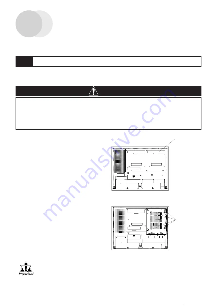
Install the VM Unit in the GP using the following steps.
1. Unplug GP unit's power cord .
2. Remove the rear face connector
cover attached to Expansion Unit
I/F 2 (EXT2).
3. Carefully insert the VM Unit into
the GP until the GP and VM Unit
connectors are securely attached.
4. Use a screwdriver to attach each of
the VM Unit's attachment screws.
(Screws are provided with VM
Unit)
Tightening torque: 0.5 to 0.6 N•m
Attachment
Screws
Connector Cover
When installing/removing the VM Unit, be careful not to lose the attach-
ment screws.
Rear Face of GP