FP2600-T11 User Manual
3-6
Installation and Wiring
Connect the FP power cable as follows:
1) Check to make sure the FP's power cord is disconnected.
2) Remove the plastic terminal cover.
3) Remove the screws from the 3 middle terminals, align the power wire connectors
and re-insert the screws. (Check each wire to make sure it is securely connected)
Use no more than 0.5 to 0.6N•m of torque to tighten the screws.
4) Replace the plastic terminal cover.
3-2-2 Precautions: FP2600-T11 Power Supply
Please pay special attention to the following points when connecting the power cable
to the Power Terminal Block at the back of the FP2600-T11 unit.
•
For between the line and ground, se-
lect a power supply that is low in
noise. If there is an excess amount of
noise, connect a noise reducing trans-
former.
Use Voltage and Noise Reduc-
ing transformers that have capaci-
ties that exceed 100VA.
•
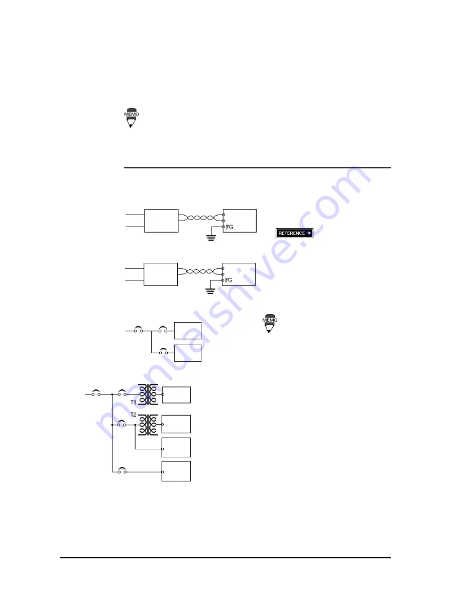
When supplying power to the FP unit,
please separate the input/output and
operation unit lines as shown in the
figure.
m a i n
power
FP
power
FP unit
Input/ Out-
put Power
power
input/output
main circuit
FP unit
input/out-
put unit
•
If the supplied voltage exceeds the FP
unit's range, connect a voltage trans-
former.
Chapter 2, "Specifica-
tions", for the allowable voltage range.
•
To increase the noise quality, simply
twist the power cable before connect-
ing it to the FP unit.
•
The power supply cable must not be
bundled or kept close to main circuit
lines (high voltage, high current), or
input/output signal lines.
•
Connect a surge absorber, as shown
in the diagram, to deal with power
surges.
•
To avoid excess noise, make the
power cable as short as possible.
FP
power
m a i n
power
Operation
Unit
Input/ Out-
put Power
FP unit
Twisted Lines
FP unit
c o n s t a n t
voltage
transformer
Twisted Lines
isolating
transformer


