PRO AIR TPK 21 Functional Description And Operating Instructions Download Page 63


58

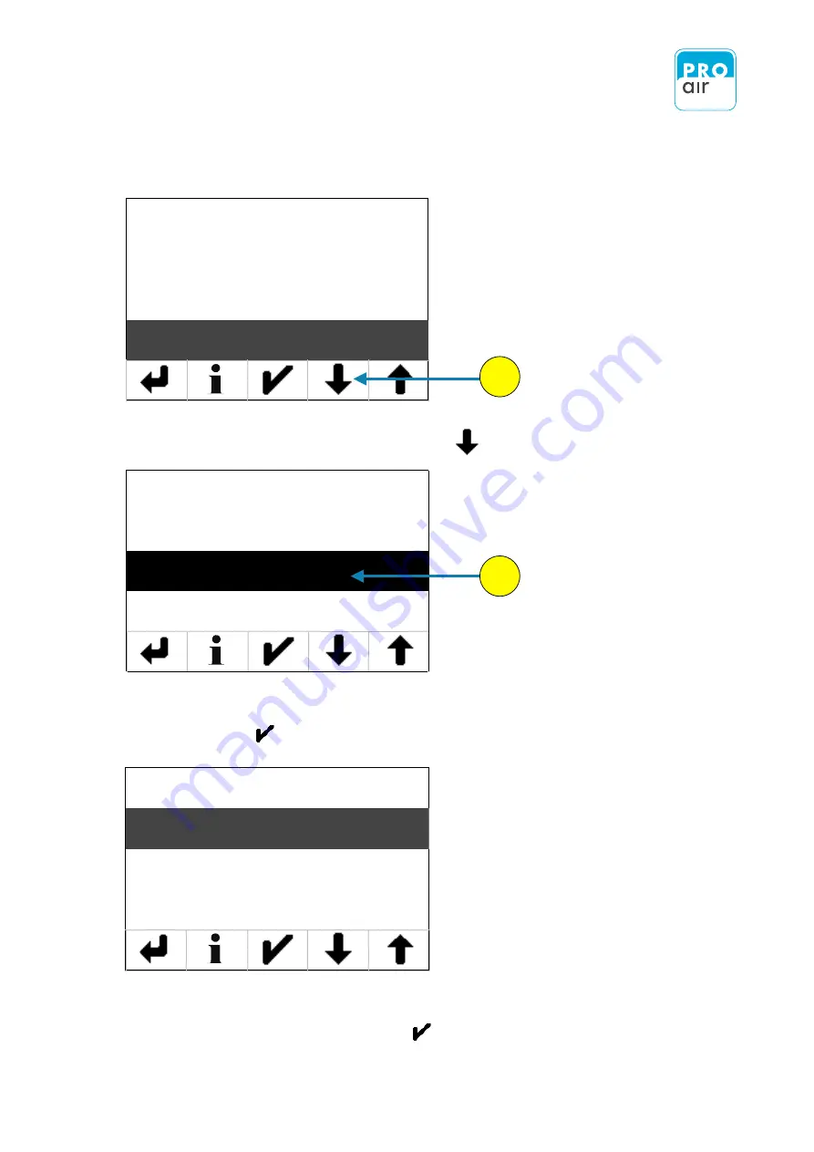
The following display of the settings menu appears (Level 3):

Password

Language

Info

Heater

8.     Please scroll down with „Scroll-down“ key       until you see the following screen. 

9.

    If the „Clear System Messages“ field is not already highlighted, select the field and  

       confirm with      . 

Yes

No

10.   Press „Yes“ or „No“ to select your desired choice. 

        Confirm your selection by pressing

        .

8

Reset Statistics

Clear System Messages

Quit Alarm

Quit Service Request

9

Summary of Contents for TPK 21

Page 1: ...Portable Pressure and Dew Point Monitoring Device TPK 21 portable TPK 61 portable Functional description and operating instructions...

Page 2: ...e 6 6 1 Safety instructions 6 6 2 Application notes 6 6 3 Procedure for installation 7 6 4 Mounting 7 7 Connection at the compressed air network 8 7 1 Direct stationary assembly at the compressed air...

Page 3: ...62 8 16 Units setting 65 8 17 Setting the Date Time 67 8 17 1 Setting the Date 67 8 17 2 Setting the Time 72 9 Configuration of Relay Adjustments 76 9 1 Setting Source Output Parameters 78 9 2 Setting...

Page 4: ...1 Menu item Main 111 15 1 2 Menu item Out 112 15 1 3 Menu item Alarm 113 15 2 System References and Messages 114 15 3 EG Conformance Details 115 15 4 Guarantee 115 15 5 Accessories 116 15 5 1 Connect...

Page 5: ...daptor stylus stylus holder which may be attached to the dew point meter and relevant operating instructions 6 4 mm PTFE compressed air hose Bypass valve to test humidity condition in the piping syste...

Page 6: ...controller and maintenance work must therefore only be carried out by trained personnel The power supply must be turned off for installation and servicing Also avoid touching the plug or any other el...

Page 7: ...g noise produced upon uncontrolled opening of pressurised lines can damage hearing or startle other people in the vicinity At high flow rates foreign bodies in the air stream can behave like projectil...

Page 8: ...int sensor is adjusted and tested by means of a complex calibration procedure involving several temperatures and humidity points It is not possible for the end user to calibrate the device Please obse...

Page 9: ...d stable long term monitoring of the humidity content This is the only way to detect problems early before any damage has occurred With its large measuring range the new TPK series is the ideal measur...

Page 10: ...he device must be mounted above the compressed air line so that any condensation produced in the event of failure cannot flood the measuring chamber Use only suitable materials The materials used must...

Page 11: ...air network The use of a PTFE or Polypropylene double nipple is an example of a suitable solution Installation involves the following steps Testing of impurities and liquid water via filter choke inc...

Page 12: ...rage Ger t ist f r eine Vielzahl von Einsatzbereichen geeignet Durch die integrierte kammer und dem flexiblen Schlauch l sst sich das Ger t leicht an den vorgesehenen z anpassen hluss an einer Schnell...

Page 13: ...ponse We can provide you with a list of suitable components upon request The device is suitable for a variety of applications The flexible design of the measuring chamber allows it to be easily adapte...

Page 14: ...Modbus on the right hand side of the device and screwed into place No complex electrical installation is necessary and the device is immediately ready for operation The AC adaptor with Europlug is of...

Page 15: ...be set For refrigeration dryers approx 0 to 7 Ctdp For an additional membrane dryer approx 20 to 10 C For an adsorption dryer approx 60 to 30 C If the device does not start up please check the follow...

Page 16: ...the description of the operating procedures All images of the displays numerical values and configurations are used by way of example to explain and clarify the information provided The actual display...

Page 17: ...nection Analog output connection Connection for external mains adapter Modbus output connection Connection for external mains adapter LCD touch display Alarm LED Service LED On Off button plug connect...

Page 18: ...white backlight and a resolution of 160 x 110 All values may be set or changed accordingly via the screen using the stylus provided or with careful finger movements Caution The use of pointed objects...

Page 19: ...be set For refrigeration dryers approx 0 to 7 Ctdp For an additional membrane dryer approx 20 to 10 C For an adsorption dryer approx 60 to 30 C If the device does not start up please check the follow...

Page 20: ...d 2 Infofeld displays the physical measuring value Info Screen temporary please notice next page Unit actual measuring value Currently measured value This field shows a further current measured value...

Page 21: ...to ambient temperature During heating HHOLD appears on the display and CHOLD is indicated during cooling The operation is indicated on the display H HOLD C HOLD The Info Screen displays the current a...

Page 22: ...inger The display now appears as follows the main field has been selected as an example In the lower third of the display an additional menu bar appears that allows further settings to be defined Klas...

Page 23: ...ppear at the bottom of the display 2 Scroll up or down to the desired setting using the two arrow keys 3 Confirm the setting using the Confirm key The display jumps back to the home screen where the m...

Page 24: ...si X X Ambient pressure bar psi X X X ppm volume concentration ppm V X X X Absolute humidity g m3 X X Alarm values settings Pre alarm Main alarm Service X X Date Time Various settings are possible in...

Page 25: ...n the loss of all settings The procedure is as follows 1 Select one of the three segment fields the background turns dark and control keys appear at the bottom of the display 1 2 PIN 1 2 3 4 5 6 7 8 9...

Page 26: ...will find all of the device settings as well as the settings for displaying the measured values 4 6 If the Device setting field is not already highlighted select the field and confirm with Under the m...

Page 27: ...e Password field is not already highlighted select the field and confirm with Select Yes to confirm and continue 8 9 10 Password Language Info Heater No Yes If you forget the password you have to send...

Page 28: ...een appears that allows you to enter a password of your choice Please confirm the new password The required input is indicated in the Password menu in the upper left corner of the display Current PIN...

Page 29: ...rectly entering the new password the display automatically jumps back to the following display The Back key takes you back to the previous level until you are back at the home screen Password Language...

Page 30: ...lect one of the three segment fields the background turns dark and control keys appear at the bottom of the display 1 2 PIN 1 2 3 4 5 6 7 8 9 0 X The following display appears 3 2 Select Settings 3 En...

Page 31: ...n field is not already highlighted select the field and confirm with Under the menu item Main you will find all of the device settings as well as the settings for displaying the measured values 4 6 If...

Page 32: ...already highlighted select the field and confirm with 10 Select the desired language the field will be highlighted and confirm your choice with 9 8 10 The Back key takes you back to the previous level...

Page 33: ...ppears 3 2 Select Settings 3 Enter your personal PIN code if it has already been changed If the device is still in its factory settings key in 111111 The procedure is as follows 1 Select one of the th...

Page 34: ...will find all of the device settings as well as the settings for displaying the measured values 4 6 If the Device setting field is not already highlighted select the field and confirm with Under the m...

Page 35: ...s information is given below FW ID Nr Ger te Seriennummer Zeit OP SRV Freier Speicherplatz auf SD Karte rH OFS T OFS sysP OFS ambP OFS Current software number Serial number of the device Current time...

Page 36: ...e trace heater should be switched on In the case of measurements at below 10 C the trace heater may be switched off if necessary The procedure is as follows 1 Select one of the three segment fields th...

Page 37: ...displaying the measured values The following display of the settings menu appears Level 2 6 If the Device setting field is not already highlighted select the field and confirm with Under the menu item...

Page 38: ...ghted select the field and confirm with The following display appears which allows you to determine the status of the heating system by selecting On or Off Confirm your entry with The Back key takes y...

Page 39: ...follows 1 Select one of the three segment fields the background turns dark and control keys appear at the bottom of the display 2 Select Settings The following display appears PIN 1 2 3 4 5 6 7 8 9 0...

Page 40: ...displaying the measured values The following display of the settings menu appears Level 2 6 If the Device setting field is not already highlighted select the field and confirm with Under the menu item...

Page 41: ...ady highlighted select the field and confirm with The Back key takes you back to the previous level until you are back at the home screen Select Yes if you want to return the device to its factory set...

Page 42: ...three segment fields the background turns dark and control keys appear at the bottom of the display 2 Select Settings The following display appears PIN 1 2 3 4 5 6 7 8 9 0 X 3 Enter your personal PIN...

Page 43: ...displaying the measured values The following display of the settings menu appears Level 2 6 If the Device setting field is not already highlighted select the field and confirm with Under the menu item...

Page 44: ...Please scroll down with Scroll down key until you see the following screen 9 If the Outputs field is not already highlighted select the field and confirm with 8 9 Password Language Info Heater Factory...

Page 45: ...d and confirm with 11 A list will appear of all the test possibilities 12 Scroll up or down using the Scroll down and Scroll up keys until you find the output value that you wish to test None Relay 1...

Page 46: ...ld is not already highlighted select the field and confirm with You can now select the status of the previously selected output NOTE For each relevant menu item you can press to call up the help text...

Page 47: ...ceed as follows 1 Select one of the three segment fields the background turns dark and control keys appear at the bottom of the display 2 Select Settings The following display appears PIN 1 2 3 4 5 6...

Page 48: ...displaying the measured values The following display of the settings menu appears Level 2 6 If the Device setting field is not already highlighted select the field and confirm with Under the menu item...

Page 49: ...rk Tap the screen until the view changes 2 Upper left corner Touch the target cross on the screen for around 2 seconds 3 Upper right corner Touch the target cross on the screen for around 2 seconds 4...

Page 50: ...ed air system in order to check the correct settings There is therefore no interference with operation The procedure is as follows 1 Select one of the three segment fields the background turns dark an...

Page 51: ...displaying the measured values The following display of the settings menu appears Level 2 6 If the Device setting field is not already highlighted select the field and confirm with Under the menu item...

Page 52: ...scroll down with Scroll down key until you see the following screen 9 If the Manual Value Override field is not already highlighted select the field and confirm with 8 9 Password Language Info Heater...

Page 53: ...the measurement parameters for which a measured value can be simulated Scroll up or down using the Scroll down and Scroll up keys until you find the Relay and Alarm output value that you wish to test...

Page 54: ...confirm with You can now enter a measured value for which the simulation should be performed NOTE For each relevant menu item you can press to call up the help text in your selected language The Back...

Page 55: ...cedure is as follows 1 Select one of the three segment fields the background turns dark and control keys appear at the bottom of the display 2 Select Settings The following display appears PIN 1 2 3 4...

Page 56: ...displaying the measured values The following display of the settings menu appears Level 2 6 If the Device setting field is not already highlighted select the field and confirm with Under the menu item...

Page 57: ...see the following screen 9 If the Reset statistics field is not already highlighted select the field and confirm with 10 Press Yes or No to select your desired choice Confirm your selection by pressin...

Page 58: ...lows the fault memory of the device to be reset This frees memory on the SD card The procedure is as follows 1 Select one of the three segment fields the background turns dark and control keys appear...

Page 59: ...displaying the measured values The following display of the settings menu appears Level 2 6 If the Device setting field is not already highlighted select the field and confirm with Under the menu item...

Page 60: ...e the following screen 9 If the Clear System Messages field is not already highlighted select the field and confirm with 10 Press Yes or No to select your desired choice Confirm your selection by pres...

Page 61: ...the alarm will be displayed again The procedure is as follows 1 Select one of the three segment fields the background turns dark and control keys appear at the bottom of the display Class ISO 8573 1 1...

Page 62: ...well as the settings for displaying the measured values The following display of the settings menu appears Level 2 Device Filter Unit Clock 6 If the Device setting field is not already highlighted sel...

Page 63: ...h Scroll down key until you see the following screen 9 If the Clear System Messages field is not already highlighted select the field and confirm with Yes No 10 Press Yes or No to select your desired...

Page 64: ...ure is as follows 1 Select one of the three segment fields the background turns dark and control keys appear at the bottom of the display Class ISO 8573 1 1 17 bar Dew Frostpoint 7 0 oC 4 Pressure 2 S...

Page 65: ...ell as the settings for displaying the measured values The following display of the settings menu appears Level 2 Device Filter Unit Clock 6 If the Device setting field is not already highlighted sele...

Page 66: ...o to select your desired choice Confirm your selection by pressing 9 If the Clear System Messages field is not already highlighted select the field and confirm with 8 Please scroll down with Scroll do...

Page 67: ...ching to the other container This can trigger alarm signals In order to prevent false alarms an appropriate filter can be used to smooth out the measured values 2 Select Settings The following display...

Page 68: ...device settings as well as the settings for displaying the measured values The following display of the settings menu appears Level 2 6 If the Filter field is not already highlighted select the field...

Page 69: ...alue 0 corresponds to unfiltered measured values The higher the selected value the slower the display It makes sense to set the filter on a scale of 0 to 20 It makes no sense to use values greater tha...

Page 70: ...the background turns dark and control keys appear at the bottom of the display 2 Select Settings The following display appears PIN 1 2 3 4 5 6 7 8 9 0 X 3 Enter your personal PIN code if it has alrea...

Page 71: ...e device settings as well as the settings for displaying the measured values The following display of the settings menu appears Level 2 6 If the Unit field is not already highlighted select the field...

Page 72: ...rement parameter Confirm your choice with At the moment there are the following choices Select the desired unit and confirm with The Back key takes you back to the previous level until you are back at...

Page 73: ...and control keys appear at the bottom of the display 2 Select Settings The following display appears PIN 1 2 3 4 5 6 7 8 9 0 X 3 Enter your personal PIN code if it has already been changed If the dev...

Page 74: ...e device settings as well as the settings for displaying the measured values The following display of the settings menu appears Level 2 6 If the Clock field is not already highlighted select the field...

Page 75: ...XAMPLE You wish to enter the date 21st March 2017 Enter the following number combination into the screen shown above 20170321 NOTE The date is always entered in the following format YYYYMMDD Year 4 di...

Page 76: ...bmenu to select the desired choices 13 If the Date Format field is not already highlighted select the field and confirm with The following display appears 15 Select the desired Date Format and confirm...

Page 77: ...urns dark and control keys appear at the bottom of the display 2 Select Settings The following display appears PIN 1 2 3 4 5 6 7 8 9 0 X 3 Enter your personal PIN code if it has already been changed I...

Page 78: ...e device settings as well as the settings for displaying the measured values The following display of the settings menu appears Level 2 6 If the Clock field is not already highlighted select the field...

Page 79: ...wish to enter the time 17 31 Enter the following number combination into the screen shown above 173100 NOTE The time is always entered in the following format HHMMSS hours 2 digits minute 2 digits Se...

Page 80: ...select the field and confirm with The following screen appears 15 Please chose the desired Time Format and confirm with 16 Leave the input field by pressing the Back key You can check your input at an...

Page 81: ...e three segment fields the background turns dark and control keys appear at the bottom of the display 2 Select Settings The following display appears PIN 1 2 3 4 5 6 7 8 9 0 X 3 Enter your personal PI...

Page 82: ...d the analog output The following display of the settings menu appears Level 2 6 If the Relay 1 field is not already highlighted select the field and confirm with The menu item Relay 1 allows all of t...

Page 83: ...e System Pressure Ambient Pressure Temperature Rel Humidity Dew Frostpoint ppm Volume Absolute Humidity Pre alarm 1 Alarm 1 Pre alarm 2 Alarm 2 Select the Source field the field will be highlighted an...

Page 84: ...teristics for Relay 1 This parameter determines whether relay can be open or closed in its initial state You may chose between the following switching characteristics Normaly closed Normaly open Alway...

Page 85: ...upper limit value is the switching point beyond which the relay switches Hysteresis Hysteresis is the difference between the switch on and switch off points at the limit value The switch on point is t...

Page 86: ...ay 3 Relay 4 return to the initial screen shown below Select the field for the relay that you wish to configure Relay 2 Relay 3 or Relay 4 Proceed in the same way as for the setting of Relay 1 see pag...

Page 87: ...ee segment fields the background turns dark and control keys appear at the bottom of the display 2 Select Settings The following display appears PIN 1 2 3 4 5 6 7 8 9 0 X 3 Enter your personal PIN cod...

Page 88: ...tings menu will appear 6 Please scroll down with Scroll down key until you see the following screen 7 If the Analog Out field is not already highlighted select the field and confirm with The menu item...

Page 89: ...nter A list appears of all of the measurement parameters for which an analogue output can be generated 3 Scroll up or down using the scroll down and scroll up keys until you reach the parameter for wh...

Page 90: ...l 1 To see the list of available output signals select 4 20 mA 0 10 V if the field is not already highlighted this will be the case once you have made the selection and confirm your choice by pressing...

Page 91: ...allows you to enter the lower value for the analog output signal The desired value must lie within the setting range selected in section 10 2 If the Setpoint 4mA 0V field is not already highlighted se...

Page 92: ...allows you to enter the upper value for the analog output signal The desired value must lie within the setting range selected in section 10 2 If the Setpoint 20mA 10V field is not already highlighted...

Page 93: ...below The procedure is as follows 1 Select one of the three segment fields the background turns dark and control keys appear at the bottom of the display 2 Select Settings The following display appear...

Page 94: ...1 field is not already highlighted select the field and confirm with Under the Men item Alarm 1 you will find all the settings for the alarm system The following screen of the settings menu will appea...

Page 95: ...ter Einheit Datum Uhrzeit None System Pressure A Pressure Temperature None System Pressure Ambient Pressure Temperature Rel Humidity Dew Frostpoint ppm Volume Absolute Humidity Pre alarm 1 Alarm 1 Pre...

Page 96: ...ff Defines whether Pre alarm 1 must be acknowledged or automatically turns itself off in the event of a limit violation Upper Limit This menu item allows you to configure the upper limit value for Pre...

Page 97: ...d The setting determines whether the upper limit for the pre alarm should be used If it is not used the following settings limit value and hysteresis are not possible Limit Value The upper limit value...

Page 98: ...e desired value and confirm with Enter If you so wish you may now enter a Hysteresis value for the upper limit value To do this select Hysteresis and confirm with Enter In the screen that follows ente...

Page 99: ...mit Lower Limit Used Limit Value Hysteresis Yes No Description Meaning Used The setting determines whether the upper limit for the pre alarm should be used If it is not used the following settings lim...

Page 100: ...the desired value and confirm with Enter If you so wish you may now enter a Hysteresis value for the upper limit value To do this select Hysteresis and confirm with Enter In the screen that follows e...

Page 101: ...confirmed with Yes or No by selecting the field in the following screen 1 2 Yes No Source Pre Alarm Main Alarm On Delay Auto Off Upper Limit Lower Limit Description Meaning Auto Off Defines whether Ma...

Page 102: ...per Limit Lower Limit Yes No Used Limit Value Hysteresis Description Meaning Used The setting determines whether the upper limit for the Main Alarm should be used If it is not used the following setti...

Page 103: ...t the desired value and confirm with Enter If you so wish you may now enter a Hysteresis value for the upper limit value To do this select Hysteresis and confirm with Enter In the screen that follows...

Page 104: ...is Auto Off Upper Limit Lower Limit Description Meaning Used The setting determines whether the upper limit for the main alarm should be used If it is not used the following settings limit value and h...

Page 105: ...t the desired value and confirm with Enter If you so wish you may now enter a Hysteresis value for the upper limit value To do this select Hysteresis and confirm with Enter In the screen that follows...

Page 106: ...eter determines the length of time between alarm condition 1 being met and actual triggering of the alarm transmitter Off Delay This parameter determines the length of time for which alarm condition 1...

Page 107: ...roll down key until you see the following screen 4 Please confirm Off Delay highlighted with Enter Enter the desired value and confirm with Enter Ger teeinstellung Filter Einheit Datum Uhrzeit 3 4 5 X...

Page 108: ...ress to call up the help text in your selected language 1 If the Alarm 2 setting field is not already highlighted select the field and confirm with To set all of the parameters for alarm value 2 proce...

Page 109: ...e humidity r F r H absolute humidity g Kg ppm by weight ppm W molecular mix ppm humidity sensor element capacitive polymer sensor analogue output active freely configurable output 4 20 mA resolution 1...

Page 110: ...asuring chamber stainless steel 1 4404 medium contacted parts display FSTN dot matrix monochrome back lit LCD touchscreen dimensions 160 x 120 x 59 mm h x b x t with coupling weight ca 600 g without p...

Page 111: ...rface ASCII over serial interface Data size RTU mode 8 ASCII mode 7 bits Stop bits 1 Parity None even odd Slave adress range 1 247 The colored items are factory settings The MODBUS communication over...

Page 112: ...To transfer the datas from the SD card onto your computer please proceed as follows 1 Please unplug the power supply otherwise you will get an failure message at the display 2 Press gently at the But...

Page 113: ...as a csv file Excel will now be able to recognise the individual tables when importing the data and doing some conversion works NOTE For simple reading of the data files we recommend our EXCEL MACRO w...

Page 114: ...to the measuring device The procedure is as follows 1 Re insert the memory card into the card slot with the gold contacts facing upwards 2 Gently press the micro SD card into the slot You will clearly...

Page 115: ...15 APPENDIX 110...

Page 116: ...s No SD free SRV OP TIME Ser Nr FW ID Nr Yes No Yes No Main Output State OFF ON None Relay 1 Relay 2 Relay 3 Relay 4 Pre Alarm Main Alarm Analog Out UMC Channel Set Value None System Pressure A Pressu...

Page 117: ...ture Rel Humidity Dew Frostpoint ppm Volume A Humidity Current Mode Voltage Mode Lower Limit Source NC NO Upper Limit Lower Limit Source NC NO Upper Limit Lower Limit Current Voltage Source Setpoint 4...

Page 118: ...System Pressure Temperature Rel Humidity Dew Frostpoint ppm Volume A Humidity Lower Limit Upper Limit Auto Off No Yes No None System Pressure A Pressure Temperature Rel Humidity Dew Frostpoint ppm Vo...

Page 119: ...larm 2 Pre alarm 2 active check compressed air system MAINAlarm 1 Main alarm 1 active check compressed air system MAINAlarm 2 Main alarm 2 active check compressed air system Sevice maintenance f llig...

Page 120: ...e product will be sold Date 08 08 2017 PKM electronic GmbH Ref No 17 07 0108 Based on Test report Ref No 17 07 0108 ACCREDITATION DESIGNATION DAkkS D PL 17379 01 00 KBA P 00088 96 ____________________...

Page 121: ...ated ball valve with the dew point meter you must use the external relay box which transfers the potential free output into the right voltage TPZKA Sensor actuator cable M 12x1 5 pin PUR halogen free...

Page 122: ...15 5 1 Connecting optional accessories 117...

Page 123: ...x 50 mA 2 WH white Light NPN switching output switches to earth 3 BU blue Earth Earth 4 BK black Signal generator NPN switching output switches to earth 5 GN YE green yellow Button Input button switch...

Page 124: ...nected to Pin 1 and Pin 2 Pin Colour Alarm Remarks 1 BN brown 24 V Operating voltage connection 24 V DC 2 WH white RS_A Voltage output 0 10 V 3 BU blue GND Power supply earth 4 BK black RS_B Current o...

Page 125: ...should be supplied with a stabilised short circuit protected and surge protected voltage source The power source of the pressure transducer must be from an energy limited source 10 A max 30 V max and...

Page 126: ...imit Value 15 0 Hysteresis 0 00 Lower Limit Used No Limit Value Hysteresis Alarm 1 Source Dew Point Pre Alarm Auto Alarm Out Upper Limit Used Yes Limit Value 12 0 Hysteresis 0 00 Lower Limit Used No L...

Page 127: ...Limit Value Hysteresis Lower Limit Used Yes Limit Value 7 50 Hysteresis 0 00 Alarm 1 Source System Pressure Pre Alarm Auto Alarm Out Upper Limit Used No Limit Value Hysteresis Lower Limit Used No Limi...

Reviews: