Air X Owner’s Manual
2
Six - Air X Installation
The following are general guidelines for the installation of Air X. Because
each wind turbine installation is unique, specific step-by-step installation
instructions cannot be provided. However, before attempting final installation
the following basic steps should be completed:
• Completely review Air X Owner’s Manual.
• Select tower and site and install tower.
See sections 3.0 and 4.0
.
• Determine wire size.
See Section 5.3
.
• Design system including batteries, switches, circuit breakers – draw
wiring diagram.
• Obtain required components.
• Assemble turbine –
See Section 2.0 Turbine Assembly
.
Once these steps are completed, final assembly is fairly simple and consists
primarily of making good electrical connections according to the wiring dia-
gram and mounting Air X on the tower.
6-1 Wire Connections to Air X
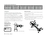
Connect wire leads from Air X to wires to be run down the tower using “split
bolt” or solder connectors. Follow good practice and use color coded wires
– red for battery positive, black for battery negative, and green for earth
ground. Wires must be sized based on turbine to battery bank distance. Refer
to
Section 5.
Insulate connections with heat shrink tubing or good quality
electrical tape. Leave sufficient service loop in the wires to accommodate
removal of the turbine from the tower. Use of an electrical wire strain relief
WARNINg:
Do not connect wires to batteries
until all electrical connections are completed.
2005 NEC Section
Topic
Article 250.52, item 5
Tower Grounding
Article 250.53, item A
Tower Grounding
Article 250.53, item G
Grounding Electrode Installation
Article 250.64
Grounding Conductor Routing and Placement
Article 250.66, item A
Grounding Conductor Size
Article 270.70
Bonding of Grounding Conductor
grip is strongly recommended for the downtower transmission wires.


