Air X Owner’s Manual
12
m
m
2
1
3
4
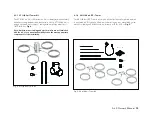
5-4 Stop Switch
MARINE uSE:
A Stop Switch is
standard equipment
with the Air X Marine.
Fig. 14. Stop Switch Assembly
recommends the use of a stop switch to provide
a convenient and safe method for shutting down your Air X. A switch is
supplied with each Air X Marine as standard equipment and is available for
purchase from
ower for the Air X Land.
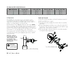
Install the switch as shown in
fig. 13
. A “break then make” switch
MuST
be
used or severe damage may occur. When wired as shown, Air X will operate
normally with the switch in the “up” position and will be “off” in the “down” po-
sition. Do not leave switch in “middle” position; this will place Air X in an open
circuit condition – see the Operating Modes section of this manual.
The stop switch model offered by Primus Wind Power is sufficient for most
systems, but it should not be used in applications where a code compliant
switch is necessary.
Volt Systems, AWG / Metric Wire Size mm
2
1.
Use either the rubber sleeved nut or the knurled nut but do not use both.
2.
Drill 12 mm (0.4725 in) hole in panel.
3.
The backing jam nut may be adjusted to allow the switch to mount flush
with the panel.
4.
No larger than 8 gauge wire should be connected directly to switch. Short
lengths (a few inches) of 8 gauge wire may be used as a transition to larger
gauge wire. Eye connectors are recommended.
5.
Wires should be supported. Provide strain relief – the switch terminals are
not designed to support lengths of wire.
BATTERY
BLACK
FUSE
WIRE
SWITCH
TURBINE
STOP
RED
WIRE
Stop Switch Assembly
NOTE: The center post
must be positive from the
turbine. Outside posts can
be swapped as either
battery positive or battery/
turbine negative.
Number of Turbines:
0-0 ft (0-2 m)
0 -20 ft (2- m)
20 -10 ft (- m)
10 -00 ft (-12 m)
1
14/2.5 mm
2
12/4 mm
2
10/6 mm
2
8/10 mm
2
2
12/4 mm
2
8/10 mm
2
6/16 mm
2
4/25 mm
2
10/6 mm
2
8/10 mm
2
6/16 mm
2
4/25 mm
2
Fig. 13. Stop Switch Wiring
Primus Wind Power
Primus Wind P
20


