22
Air X Owner’s Manual
The following section (5-8) describes grounding the tower in detail. To
ground the Air X turbine body, connect the Air X ground (green) conductor
to the tower ground rod. Alternately the ground (green) conductor may be
connected to the negative (black) conductor in which case it will be ground-
ed through the battery bank ground rod. Refer to figures 9 through 12.
Note that all system grounds should be connected using conductors of the
same size as the positive and negative wires.
If you choose to not set up an earth ground system (not required for
systems under 50 volts), the Air X green and black conductors MUST be
connected to each other or severe damage to Air X may result and void
your warranty. Grounding is necessary to lessen the potential for EMI
grounded according to American boat and yacht Council recommenda-
tions. There are special grounding requirements for boats, in particular
boats that connect to shore AC power, that MuST be observed or a
serious shock hazard may result. Contact the American boat and yacht
Council.
5-8 Tower grounding
Every wind turbine and turbine tower should be grounded at the tower base
even though the system may be grounded at the battery bank or service
panel by means of the yaw ground lead. Grounding the tower at its base
may prevent shocks to persons touching the tower due to lightning or
electrical faults.
The following sections are provided as a guide to properly grounding the
tower and should not be considered completely comprehensive. You are
encouraged to reference the National Electrical Code (NEC) and local
building and zoning regulations for complete requirements. Relevant sec-
tions of the National Electrical Code are referenced.
Tower grounding may be accomplished in several ways; the most common
method is a copper clad steel electrode(s) driven into the soil and con-
nected to the tower using a wire conductor.
5-8-1 Electrodes driven in Soil
Electrodes should be a minimum of 8 ft (2.5 m) in length and free of non-
conductive coatings such as paint. Hollow electrodes of pipe or conduit
should not be smaller than trade size 3/4 (metric designator 21) and must
be galvanized or otherwise protected from corrosion. Solid rod electrodes
must be at least 5/8 inch (16 mm) diameter. Stainless steel rods less than
5/8 inch diameter, nonferrous rods or their equivalent less than 1/2 inch
diameter shall be “listed” by an organization having jurisdiction in the area.
For example: UL in the USA and CSA in Canada.
Electrodes shall be installed such that 8 ft (2.5 m) is in contact with the soil.
They should be driven into undisturbed soil within 1 ft of the tower founda-
tion. Electrodes should be driven to a depth of 8 ft (2.5 m) except where
rock is encountered; then the electrode may be driven at an angle not to
exceed 45 degrees from vertical. Some local authorities permit burial of
the electrode in a trench that is a minimum of 30 inch (76 cm) deep.
The upper end of the electrode and its connection to the grounding con-
ductor should be below grade or if above ground, must be protected from
damage.
Bonding the grounding conductor to the electrode and to the tower may
be accomplished by exothermic weld or by a “listed” mechanical connec-
tor. Solder connections are not permitted. Most local authorities require a
minimum grounding conductor size of 6 AWG for copper and 4 AWG for
aluminum (if aluminum is permitted).
The grounding conductor may be buried directly or contained in conduit;
in either case it is important that it have no sharp bends to keep its induc-
tance low.
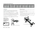
The accompanying figure (see page 23) depicts a typical tower grounding
interference with electronics.
Primus Wind Power strongly recommends that boat installations be
technique and the following sections of the NEC are listed for reference.

