10
Chapter 1 Component Names and Functions
1.1 Server (Front View)
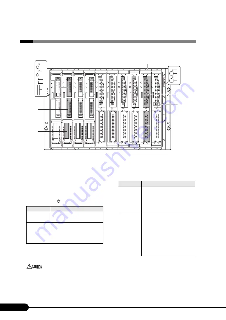
The following are the component names of the server (front view).
8
9
7
12
11
10
14
13
2
1
3
4
5
6
*:The Server Blade diagram shown in this manual shows one possible setup pattern.
15
16
1
Server blade slots 1-10
This is where server blades or dummy server blades are
installed. The server blade slot numbers are displayed
on the chassis.
A total of nine dummy server blades come included
with the chassis by default. Server blades are not
included with the chassis by default.
2
Main power LED (
)
3
Main Power Switch
Pressing this switch starts the system fan unit and the
Switch Blades.
Do not turn the server off when the hard disk
access display LED is on. The data stored on the
hard disk may be damaged.
LED status
Server Status
ON (Green)
The main power supply of the chassis
is ON.
ON (Amber)
The AC power is ON but the main
power supply of the chassis is OFF.
OFF
The main power supply or the AC
power of the chassis is OFF.
4
Front maintenance switch LED (
)
This works in conjunction with the rear maintenance
LED and lights/blinks in the following situations.
5
Front maintenance switch
Pressing this switch turns the front and rear maintenance
switch LEDs ON.
ID
LED status
Server Status
Blinking
(Amber)
An error in an internal component of
the server has been detected.
Contact an office listed in the
"Contact Information" of "Start
Guide" or device administrator.
ON (Amber)
This can be turned on by pressing the
front maintenance switch or using the
"System Indication LED Display"
function in the management terminal.
For details about the "System
Indication LED Display" function
refer to "BX600 Management Blade
Hardware Guide" and "ServerView
User's Guide".


