Section 12: BRAKE AND AIR SYSTEM
Section 12 Updated Sept. 2015
X3-45 Commuter PA1593 DOB 2400-2489
21
only enough to stop leakage.
Do not
overtighten
as this can distort sealing
surface or clamping ring. Coat area around
push rod hole (loosen boot if necessary). No
leakage is permitted. If leakage is detected,
the diaphragm must be replaced.
30.2
EMERGENCY/PARKING BRAKE
MANUAL RELEASE
DANGER
Never stand in the axis line of the spring brake
chambers, especially when caging the spring.
Drive Axle
1. Block the wheels to prevent the vehicle from
moving.
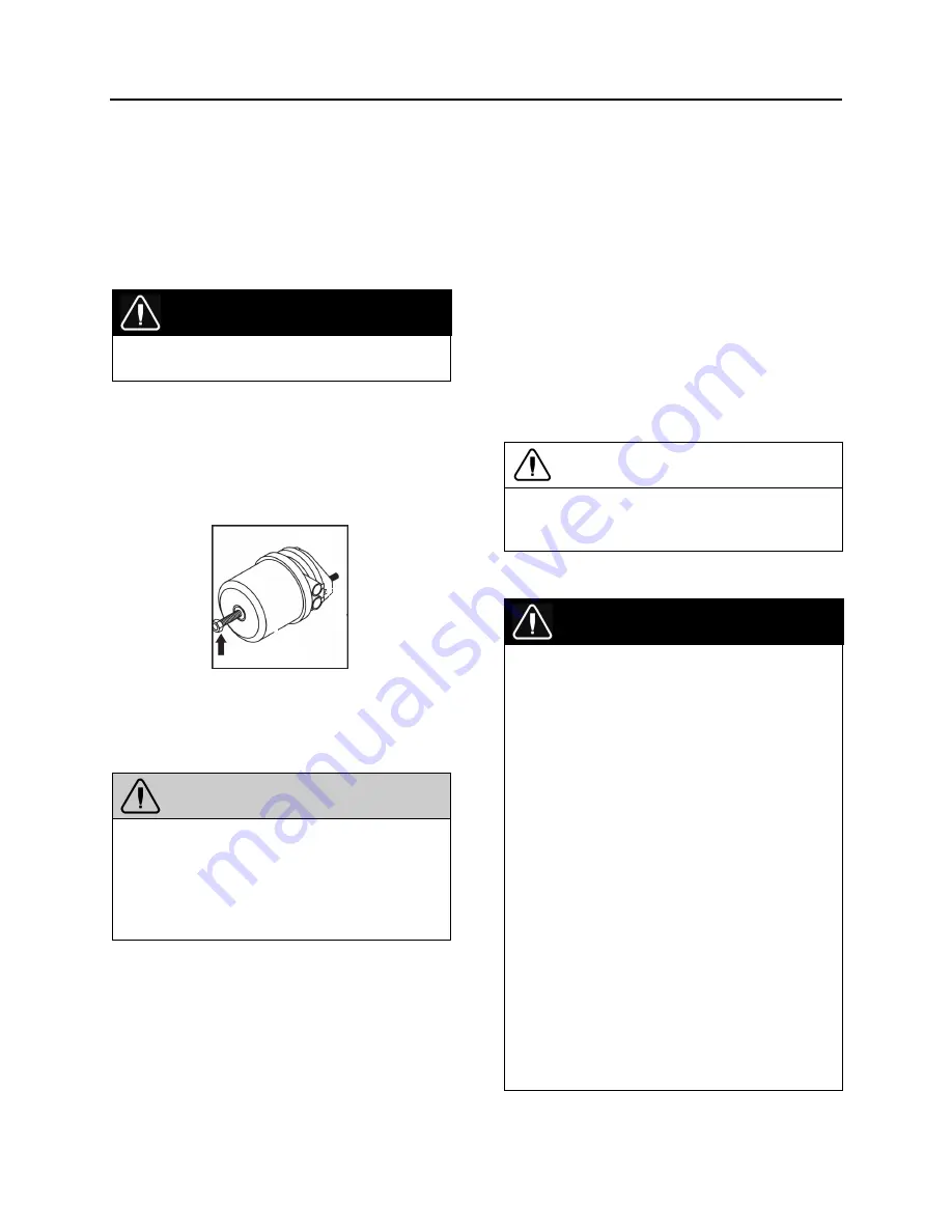
2. Screw-out the spring brake release bolt
(arrow) with a maximum of 26 lbf-ft (35 Nm)
to the release position.
3. To manually reset the emergency/parking
brake, screw in the spring brake release bolt
with a maximum of 52 lbf-ft (70 Nm).
30.3
BRAKE CHAMBER REMOVAL
WARNING
To prevent personal injuries, brakes should be
inoperative prior to working on any of their
components.
To prevent personal injuries, brake chambers
should be made inoperative by releasing
spring tension prior to disposal.
1. Block the wheels to prevent the vehicle from
moving.
2. Safely support vehicle at the recommended
body jacking points.
3. To gain access to a given brake air
chamber, the corresponding wheel can be
removed (refer to Section 13:
"Wheels, Hubs
and Tires"
).
4. Exhaust compressed air from system by
opening the drain valve of each reservoir.
5. For the drive axle brake chambers, manually
release spring brakes (refer to
"
Emergency/Parking Brake, Manual
Release"
procedure in this section).
6. Disconnect air line(s) from brake chamber.
7. Remove the cotter pin connecting brake
chamber and slack adjuster (drive axle).
8. Unbolt and remove the brake chamber from
vehicle.
30.4
BRAKE CHAMBER INSTALLATION
Reverse removal procedure and then check
brake adjustment.
CAUTION
Always clean air lines and fittings, and coat
pipe threads with teflon pipe sealant before
reconnecting air lines.
30.5
BRAKE CHAMBER DISASSEMBLY
DANGER
Spring brake chambers, on drive and tag axles
contain an extremely high compressive force
spring, which can possibly cause serious injury
if special precautions are not taken when
working around this area.
To avoid such injury, the following recommen-
dations must be applied:
o
Prevost recommends the installation of a
new spring brake chamber if it is found to
be defective.
o
Spring brake chamber maintenance and/or
repair must be performed by trained and
qualified personnel only.
o
Before manually releasing spring brakes,
visually check spring brake for cracks
and/or corrosion.
o
On “MGM” brake chambers (drive axle),
make sure the release stud is properly
anchored in spring plate receptacle prior to
caging the spring.
o
Never stand in the axis line of the spring
brake chambers, especially when caging
the spring.
Summary of Contents for X3-45 2016
Page 4: ......
Page 16: ...Section 00 GENERAL INFORMATION PA1593 12 FIGURE 12 METRIC US STANDARD CONVERSION TABLE 00005...
Page 17: ...Section 00 GENERAL INFORMATION 13 PA1593 FIGURE 13 CONVERSION CHART 00006...
Page 18: ......
Page 26: ......
Page 58: ......
Page 72: ...Section 04 EXHAUST AND AFTERTREATMENT SYSTEM PA1593 14 7 TORQUE SPECIFICATIONS...
Page 73: ...SECTION 04 EXHAUST AND AFTERTREATMENT SYSTEM PA1593 15...
Page 74: ...Section 04 EXHAUST AND AFTERTREATMENT SYSTEM PA1593 16...
Page 76: ......
Page 96: ......
Page 134: ......
Page 176: ...SECTION 06B ELECTRICAL 38 overcurrent working Circuit 306 shorted to ground...
Page 180: ......
Page 202: ......
Page 205: ...Section 09 PROPELLER SHAFT PA1593 3 FIGURE 1 PROPELLER SHAFT ASSEMBLY 09002...
Page 256: ......
Page 268: ......
Page 295: ...SECTION 16 SUSPENSION PA1593 9 2 5 TORQUE SPECIFICATIONS...
Page 296: ...Section 16 SUSPENSION PA1593 10...
Page 297: ...Section 16 SUSPENSION PA1593 11...
Page 314: ......
Page 380: ......
Page 388: ......
Page 413: ...Section 22 HEATING AND AIR CONDITIONING PA1593 15 FIGURE 18 REFRIGERANT CIRCUIT CENTRAL SYSTEM...
Page 433: ...Section 22 HEATING AND AIR CONDITIONING PA1593 35 FIGURE 36 CENTRAL HEATING SYSTEM COMPONENTS...


