PRESYS
Instruments
DMY-2030-TOT
Light
Operation
Page 22
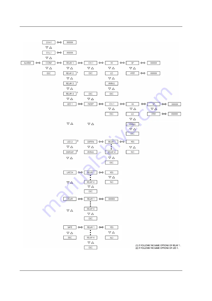
Fig. 15 - ALARM level options
presys
Page 1: ...DMY 2030 TOT Process Indicator and Totalizer Light Instruments Inc PRESYS TECHNICAL MANUAL PRESYS DMY 2030 TOT LD1 LD2 Light p r e s y s ...
Page 2: ...immunity standard EN 50082 2 1995 Performance criterion B EN 61010 1 1993 Safety Considerations I have made all reasonable enquiries regarding the unit stated and their conformance to the EU Low Voltage and EMC Directives To the best of my knowledge and belief this unit conform to these directives This Declaration is controlled under an ISO 9001 2000 system certificated by TÜV Rheinland certificat...
Page 3: ...e Input 8 2 3 2 Volt or Millivolt Input 9 2 4 Output Signal Connections 9 2 5 Connection Diagram 11 2 6 Communication 12 2 7 Engineering Units 12 3 0 Operation 13 3 1 Normal Operation 13 3 2 Configuration 14 4 0 Maintenance 27 4 1 Indicator Hardware 27 4 2 Hardware Configuration 28 4 3 Snubber use for relay 29 4 4 Option Module Connection 30 4 5 Calibration 34 4 6 Hardware maintenance instructions...
Page 4: ...ation is performed with 8 digit count configured together with the number of decimals The totalization counts do not decrease for signals under the zero scale defined by the user and Reset can be applied to the totalization by means of the Indicator front panel keys or by the contact input Input type is enabled by jumpers and software configuration All configuration data is stored in non volatile ...
Page 5: ...ivate them after the process variable returns to normal condition One retransmitter output is available to provide a linear output signal from 4 to 20 mA 1 to 5V or 0 to 10V proportional to the input process variable being measured This signal allows the retransmittion of the variable to a distant location When using the analog output up to three alarm modules can be used 1 2 Order Code DMY 2030 T...
Page 6: ...software features can be available under previous consult Code example 1 DMY 2030 TOT Light 0 0 1 1 1 0 0 This code defines a DMY 2030 TOT Light Indicator and Totalizer with two SPDT relays which can be used as high and low alarms 90 to 240VAC or 130 to 340VDC electric power supply protected field usage 1 3 Technical Specifications Input One input configurable for 4 to 20 mA 0 to 55 mVdc 1 to 5 Vd...
Page 7: ...oard Indication Indication with 999 to 19999 range Totalization Input totalization with 0 to 99999999 range configured with decimal point Configuration By front panel pushbuttons and internal jumpers Sampling rate 130 ms for input indication in 999 to 19999 range The display is updated each second for the indication and each scan for the totalization Accuracy 0 1 of full scale for mA mV Vdc input ...
Page 8: ...PRESYS Instruments DMY 2030 TOT Light Introduction Page 5 Dimensions 1 8 DIN 48 X 96 mm with 162 mm depth panel cutout of 45 X 92 mm Weight 0 5 kg approx Warranty One year warranty p r e s y s ...
Page 9: ...gh the cut until its front reaches the panel Place the rails again in the Indicator from the back of the panel and tighten the screws as shown in figure 2 Fig 2 Dimensional drawing panel cutout and side view 2 2 Electrical Installation DMY 2030 TOT Light Indicator and Totalizer may be powered by voltage between 90 and 240VAC or 130 to 340VDC any polarity Remember that the internal circuit is power...
Page 10: ... and ranges of input sensors in table 1 section 1 3 on Technical Specifications The input sensor is enabled by internal jumpers see section 4 2 on Hardware Configuration and by selection of the sensor in the software see section 3 2 on Configuration The connections explained below will have the desired result only if the instrument is correctly configured by software and hardware In order to avoid...
Page 11: ...erminals 1 and 3 The current signal can be generated by a transmitter with an external power supply In case of using the 24 VDC internal voltage source from the Indicator to power a two wire transmitter the current is received only by terminal 1 Figure 4 shows both possibilities of connection Fig 4 Milliampere Input p r e s y s ...
Page 12: ...igure 5 Fig 5 Volt or millivolt Input 2 4 Output Signal Connections The Indicator can have up to four output signals output 1 output 2 output 3 and output 4 Output 1 is used as retransmitter or alarm output Outputs 2 3 and 4 are used only as alarm outputs For output 1 there are six different types of outputs available retransmitter 4 to 20mA 0 to 5Vdc or 0 to 10Vdc SPST relay open collector voltag...
Page 13: ...e optional modules are installed and the output is correctly configured For analog outputs refer to section 3 2 on Configuration and section 4 4 on Optional Module Connection for details on installation and configuration of optional modules Relay contact states shown are valid for SAFE option selected see section 3 2 on Configuration instrument powered on and non alarm condition Positions of the c...
Page 14: ...PRESYS Instruments DMY 2030 TOT Light Installation Page 11 2 5 Connection Diagram p r e s y s ...
Page 15: ...e when the optional communication module is installed and the communication parameters are configured Specific information on communication and signal connection is described in the communication manual 2 7 Engineering Units A label with several Engineering Units is supplied with each Indicator Select the one corresponding to the variable shown on the display and stick it to the front panel of the...
Page 16: ...lay When the process variable is shown after pressing the DOWN key the display presents the totalization By pressing again the DOWN key the indication is shown UP Key When showing the indication it presents the alarm outputs which require acknowledgment to return to normal state When showing the totalization it allows accessing a menu with options for configuring the preset mode automatic or manua...
Page 17: ...tion mode one of the following events can happen depending on the current configuration i To access directly level 1 GENERAL of configuration mode which indicates the instrument was not configured with a password system ii To display the PASS warning indicating that the instrument is provided with a password system a key sequence or a value according to figure 8 Fig 8 Password through key sequence...
Page 18: ...cedure above is valid for providing any other parameter with 5 digits The only exception is COUNT parameter in Totalization level for which it is possible to change all the 8 digits of the display All configuration parameters are stored in the non volatile memory and determine the normal operation of the instrument With these parameters the user can adjust the instrument to his needs when it is ne...
Page 19: ...equence is obtained by pressing the UP DOWN and ENTER keys in this order INDC is an option for the visualization of the measured variable and totalization on the display It allows the user to view the values of the indication and totalization only by pressing the UP and DOWN keys or it sets the instrument to change automatically the indication and totalization In order to enable the automatic scan...
Page 20: ...in figure 10 Mnemonic Parameter Range Factory Value Units TAG instrument identification 0 to 30000 2030 ____________ SOFT software version _______________ 1 41 ____________ VALUE user password 9999 to 30000 0 ____________ TIME1 process variable exhibition time 0 to 3000 5 seconds TIME2 totalization exhibition time 0 to 3000 1 seconds p r e s y s ...
Page 21: ...NPUT Level allows to choose the sensor type for the input channel 1 The sensor type options are 0 to 5V 0 to 10V 0 to 55mV and 0 to 20mA as illustrated in figure 11 4 to 20mA input belongs to 20mA option 1 to 5V input belongs to 5V option Fig 11 INPUT level options p r e s y s ...
Page 22: ...root 0 to 5 0 OFFSET constant added to display indication 9999 to 30000 0 EU FILTER time constant of 1 st order digital filter 0 0 to 25 0 0 0 seconds EU Engineering Unit When selecting a linear sensor one must configure its scale SCALE option Define two points P1 Lim Low Eng Low and P2 Lim High Eng High as illustrated in figure 12 Lim Low represents the value of the electrical signal given in of ...
Page 23: ...o the selected input In order to leave the signal without filter set this parameter to zero Level 3 Alarm The Indicator has up to seven alarm devices four of them are the outputs 1 2 3 and 4 used as alarm outputs which are relay 1 relay 2 relay 3 and relay 4 The other three devices are the couple of leds LED 1 and LED 2 and the display which can operate independently from the relays In this case t...
Page 24: ...nding to the relay one is looking for Note that it will be shown only the relays configured with latch operation which require acknowledgment in order to return to normal state After reaching the relay press the ENTER key If there is no alarm condition for this relay it will change its state Continue pressing the UP key to return to operation mode DELAY causes the relay to be activated only after ...
Page 25: ...PRESYS Instruments DMY 2030 TOT Light Operation Page 22 Fig 15 ALARM level options p r e s y s ...
Page 26: ...0 0 0 seconds Level 4 Output Level 4 allows the configuration of one analog output Refer to figure 16 Fig 16 OUTPUT level options The table below refers to the ranges of the parameters shown in figure 16 Mnemonic Parameters Range Factory Value Unit LIM LOW output signal associated to Eng Low 0 0 to 100 0 0 0 LIM HIGH output signal associated to Eng High 0 0 to 100 0 100 0 ENG LOW display indicatio...
Page 27: ...igh Note that Lim Low and Lim High are defined in percentage of output range and that the output signal saturates in these points FULL SCALE OUTPUT SIGNAL Fig 17 Analog output configuration Level 5 Totalization In level 5 it is configured the totalization of the process variable for 5V 10V 55mV and 20mA linear inputs The integration is performed according to the percentage of the input signal in r...
Page 28: ...ME when there is a signal of 100 FS in the input 0 to 99999999 0 TIME Interval of time after which the totalization is increased by COUNT when there is a signal of 100 FS in the input 0 to 30000 0 min SP Count for the preset in order to reset the totalization and activate the relay 0 to 99999999 0 RL PULSE Interval of time during which the relay remains activated after the SP count for the preset ...
Page 29: ...t function select the YES option for the mnemonics chosen among RELAY1 to RELAY4 in the RELAY option For the preset to operate without relay select the ANUL mnemonic The preset allows the reset of the totalizaton in automatic or manual mode configured in the MODE option When the totalization reaches the preset setpoint SP in the automatic mode the totalization is reset and the associated relays ar...
Page 30: ...e instrument from case The Display Board is located in the Indicator front panel The front panel has four internal staples in its four corners which keep together CPU and Power Supply Boards The CPU and Power Supply Board are fixed by a spacer i Remove the screw which fixes the spacer placed near the edge of the CPU and Power Supply Boards ii Turn the Indicator so that the display is on the opposi...
Page 31: ...umpers in the CPU Board Table 2 lists the jumpers that must be installed for each type of input Verify the input type required and place the jumpers as specified below Make sure to install only the jumpers required for the input Input type Jumpers Channel 1 Voltage 0 to 55mV J5 J7 Voltage 0 to 5V J5 J7 Voltage 0 to 10V J6 Current 0 to 20mA J6 J7 Table 2 Jumpers for input type configuration For 0 t...
Page 32: ...ety of industrial processes In order to ensure the expected relay behavior consider the following two loading conditions High currents circulating through the relay contacts from 20mA to 3A When the relay switches high currents there is the occurrence of electrical arch which damage quickly the relay contacts Besides electrical noise is generated In these conditions it is recommended to use the RC...
Page 33: ...er Supply Board and one connector in the CPU board Refer to Figure 23 Fig 23 Optional module connectors The connectors in the Power Supply Board are called MOD 1 MOD 2 MOD 3 and MOD 4 and are associated in this order to output 1 output 2 output 3 and output 4 signals in the Indicator output terminals as shown in Figure 3 The connector for the communication module is placed in the CPU Board and has...
Page 34: ...mpers in analog output board In order to configure the optional analog output module as a retransmitter output for 4 to 20mA 1 to 5V or 0 to 10V install the jumper according to table 3 Retransmitter Output Type Jumpers 4 to 20mA 1 to 5V J1 0 to 10V J2 Table 3 Jumper for retransmitter output type configuration In case of 4 to 20mA current retransmitter output keep the jumper out of the instrument o...
Page 35: ...PRESYS Instruments DMY 2030 TOT Light Maintenance Page 32 state relay and the open collector voltage The alarm output type and the optional module code are listed in table 4 p r e s y s ...
Page 36: ...and 4 are used as alarms when the optional modules corresponding to connectors MOD 3 and MOD 4 are installed There are three types of alarm output available SPDT relay solid state relay and open collector voltage The Alarm output type and the optional module correspondence are shown in table 5 Alarm Output Type Optional Module Code SPDT Relay MALRE 20 Solid state relay MALRS 20 Open collector volt...
Page 37: ...ng this level is number 5 Once the correct password is provided select the input type to be calibrated Choose channel 1 by pressing ENTER The display shows the mnemonics related to the references required for the calibration process The references must be applied before selecting the corresponding mnemonic shown on display When the reference is stable start the calibration by pressing ENTER At thi...
Page 38: ...g 26 CALIBRATION level options Calibration of voltage input 0 to 55mV In a 0 to 55mV voltage input calibration connect a voltage source to terminals 2 and 3 It is required 6 voltage references listed in table 6 Reference Mnemonic 0 000 mV C 0nV 10 000 mV C 10nV 20 000 mV C 20nV 30 000 mV C 30nV 40 000 mV C 40nV 50 000 mV C 50nV p r e s y s ...
Page 39: ...PRESYS Instruments DMY 2030 TOT Light Maintenance Page 36 Table 6 References for 0 to 55V input calibration p r e s y s ...
Page 40: ... 10V voltage input calibration connect a voltage source to terminals 1 and 3 It is required 6 voltage references listed in table 8 Reference Mnemonic 0 0000V C 0V 2 0000V C 2V 4 0000V C 4V 6 0000V C 6V 8 0000V C 8V 10 0000V C 10V Table 8 References for 0 to 10V input calibration Calibration of current input 0 to 20mA In a 0 to 20mA current input calibration connect a current source to terminals 1 ...
Page 41: ...ss ENTER The display will show the mnemonic related to the first point of calibration There are only two points for output calibration For current output the mnemonics are related to 0 and 20mA electric signals For voltage output the mnemonics are related to 0 and 5V or 0 and 10V signals Press ENTER after the display shows the mnemonic related to first or second point of calibration so that the di...
Page 42: ...uration the display can show the Err 03 error message This error can happen when trying to assign a different configuration analog output alarm or preset to an output already configured and enabled In order to avoid this case do not forget to disable relay 1 before enabling analog output 1 and vice versa Note When configuring a relay module as an analog output the relay will be activated and deact...
Page 43: ...9 and point 8 8V Between point 9 and point 1 0V Between point 9 and point 10 8V Between point 9 and point 13 24V Between point 12 and point 11 5V Table 11 Inspection points of voltage on flat cable 1 Fig 27 Voltage test points of the Indicator If the cause of the problem was not discovered the Indicator must be sent to factory p r e s y s ...
Page 44: ...ilayer Capacitor 0 01µF x 63V C24 01 03 0039 21 Polyester Capacitor 0 1 µF x 250 V C1 3 01 03 0022 21 Polyester Capacitor 0 01 µF x 100 V C15 17 01 03 0041 21 Polyester Capacitor 0 01 µF x 250 V C4 5 01 03 0042 21 Radial Electrolytic Capacitor 22 µF x 25 V C9 C10 01 03 0027 21 Radial Electrolytic Capacitor 100 µF x 25 V C18 21 01 03 0043 21 Radial Electrolytic Capacitor 100 µF x 35 V C16 22 01 03 ...
Page 45: ...c Disc Capacitor 56pF x 50 V 4 mm C18 19 01 03 0035 21 Ceramic Multilayer Capacitor 0 1µF x 63V C1 4 5 6 7 8 9 10 11 12 C13 20 21 22 24 25 27 C29 30 32 33 34 35 36 C37 38 41 42 43 44 01 03 0039 21 Polyester Capacitor J 5 0 1 µF x 250 V C39 01 03 0038 21 Radial Electrolytic Capacitor 10µF x 16 V C28 23 26 31 01 03 0027 21 Radial Electrolytic Capacitor 100µF x 25 V C40 01 02 0103 21 Resistor 68R1 1 ...
Page 46: ... 1 01 03 0035 21 Ceramic Multilayer Capacitor 0 1µF x 63 V C5 6 01 03 0011 21 Ceramic Multilayer Capacitor 220pF x 63V C4 7 01 03 0050 21 Tantalo Capacitor 1µF x 35V C 2 3 01 02 0008 21 Resistor 49R9 1 R 4 01 02 0010 21 Resistor 100R 1 R 5 01 02 0013 21 Resistor 249R 1 R 10 11 01 02 0115 21 Resistor 402R 1 R 13 01 02 0024 21 Resistor 2K 1 R 9 01 02 0029 21 Resistor 4K02 1 R 2 01 02 0038 21 Resisto...
Page 47: ...omponents List of recommended spare components Display Board Display DP1 2 3 4 5 6 7 8 Power Supply Board IRF 822 Q3 UC 3842 U1 Fuse 2A F1 LM 1458N U2 I O Terminal Board BC 337 U1 CPU Board 4051 U14 4053 U15 Reference diode LM336 5V Z1 Engineering Units Label Code 02 10 0003 21 p r e s y s ...
Page 48: ...www presyscorp com p r e s y s ...