


PRESTO
GmbH & Co. KG
Bad Laer
04/2012 7 - 4
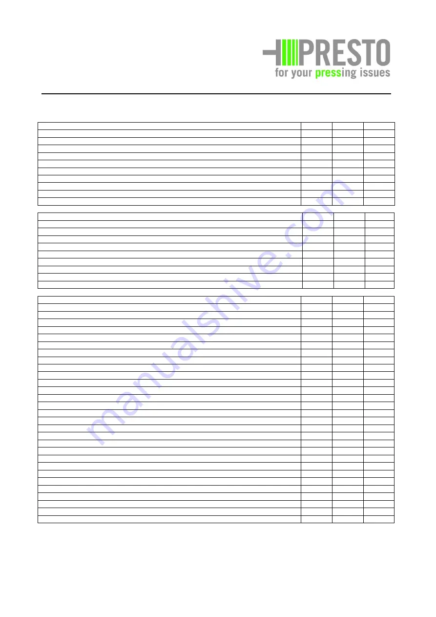
Electrical system
Interval Page Resp.
person
Controls on the switch cabinet and control bar: function check
T
A
Main switch and Emergency OFF switch: function check
T
7-17
A
Motor protection relay: function check
J
7-14
F
Wiring in the switch cabinet and on machine housing: visual check
J
7-10
F
Power cable: visual check
W
7-10
A
Safety switch on side service doors, needle hatches: function check
T
7-9
A
Safety switch on twister hood: function check
T
7-9
A
Safety switch on service door in the hopper: function check
T
7-8
A
Terminal position switch for emergency pull line (optional): function check
W
A
Ventilation hood on electrical motor: check for cleanliness
T
A
Automatic start system (optional): check function and cleanliness
W
A
Hydraulic system
Hydraulic aggregate and fittings: check condition and tightness
H
A
Hydraulic oil: check condition and oil level and refill if necessary
M
7-11
A
Filter insert and ventilation filter: replace
J
F
Hydraulic hoses and fittings: check condition and tightness
H
A
Hydraulic lines and fittings: check condition and tightness
H
7-15
A
Hydraulic valves: check tightness
H
A
Hydraulic cylinder (main, needle, twister, channel): check tightness and condition
H
7-16
A
Compaction pressure: check setting acc. to specification
J
F
Other hydraulic accessories: check function and tightness
H
A
Oil change
J
7-17
F
Mechanical system
Plunger: check condition and wear
J
F
Plunger setting in channel: check and adjust if necessary
M
A
Polyamide guides on plunger: check for wear
M
7-14
A
Telescoping sheets: check the condition
J
F
Polyamide telescoping sheet guides: check condition and wear
M
7-14
A
Cutting gap on the plunger: check and adjust if necessary
W
7-12
A
Counter-blade and blade on the plunger: check condition and wear
W
7-18
A
Compaction channel floor: check condition and wear
J
F
Needle guide rollers: check cleanliness and wear
W
A
Needle head: check condition and wear
M
A
Binding system: check function and cleanliness
T
A
Twister disks: check the setting
T
7-13
A
Twister chain: check the condition, lubricate, adjust and re-tension if necessary
M
7-13
A
Twister blade: check wear and movability
W
A
Polyamides in the twister: check for wear
J
F
Retainer: check function
W
7-19
A
Locking pins on hydraulic cylinder: check wear and lubricate
J
F
Press bar on channel outlet: check the securing pin
W
A
Guides for binding wire and binding strap: check free run
W
A
PVC cover on channel outlet: check the condition
H
A
Service doors, twister hood, service and cleaning hatches: lubricate
J
F
Moving parts on compactor: check movability and lubricate
J
F
Ground anchors of the compactor: check firm seat
J
F
Service doors, protection hoods and cover panels: check the condition
M
A
Hopper: check the condition
J
F
Overall condition of the compactor's welded construction: check the condition
J
F
Bolted connections in general: check for firmness
T
7-7
A
Labels: check condition and legibility
H
A
Overall condition of the machine's welded construction: visual check
W
A
Other accessories (optional): check condition and function
W
7-10
A
Note:
Maintenance works, as far as they concern special equipment, are described in chapter 11 "Appendix, special equipment".


